Low-voltage coil winding tool for transformer

A technology of low-voltage coils and transformers, applied in the field of transformers, can solve the problems of starting deviation, wasting time, affecting product quality, etc., and achieve the effect of improving product quality, reducing quantity, and reliable compression

Inactive Publication Date: 2016-02-24
重庆吉能变压器有限公司
View PDF0 Cites 6 Cited by
  • Summary
  • Abstract
  • Description
  • Claims
  • Application Information

AI Technical Summary

Problems solved by technology

The winding of the low-voltage coil can be completed by rotating the winding machine shaft 10 during winding. It can be seen that the fixing block 15 must be installed and disassembled every time a low-voltage coil is wound, which is a waste of time.
Furthermore, the cross-section of the low-voltage coil mold of transformers with different capacities is different, and the coils of small transformers generally use one flat copper wire with insulation, while large transformers use multiple flat copper wires with insulation, so different capacities The low-voltage coil winding of the transformer requires different baffles, or one baffle is used for several similar capacities, but when winding coils with different capacities, it is necessary to add pads of different heights at the corresponding positions (point A) of the baffle, which is most The manufacturer's method of use, however, this method of use leads to poor fixation effect, which may easily cause deviation at the beginning and affect product quality

Method used


Image

  • Low-voltage coil winding tool for transformer
  • Low-voltage coil winding tool for transformer
  • Low-voltage coil winding tool for transformer

Examples


Embodiment Construction

[0015] In order to make the technical means, creative features, goals and functions achieved by the present invention clearer and easier to understand, the present invention will be further elaborated below in conjunction with the accompanying drawings and specific embodiments:

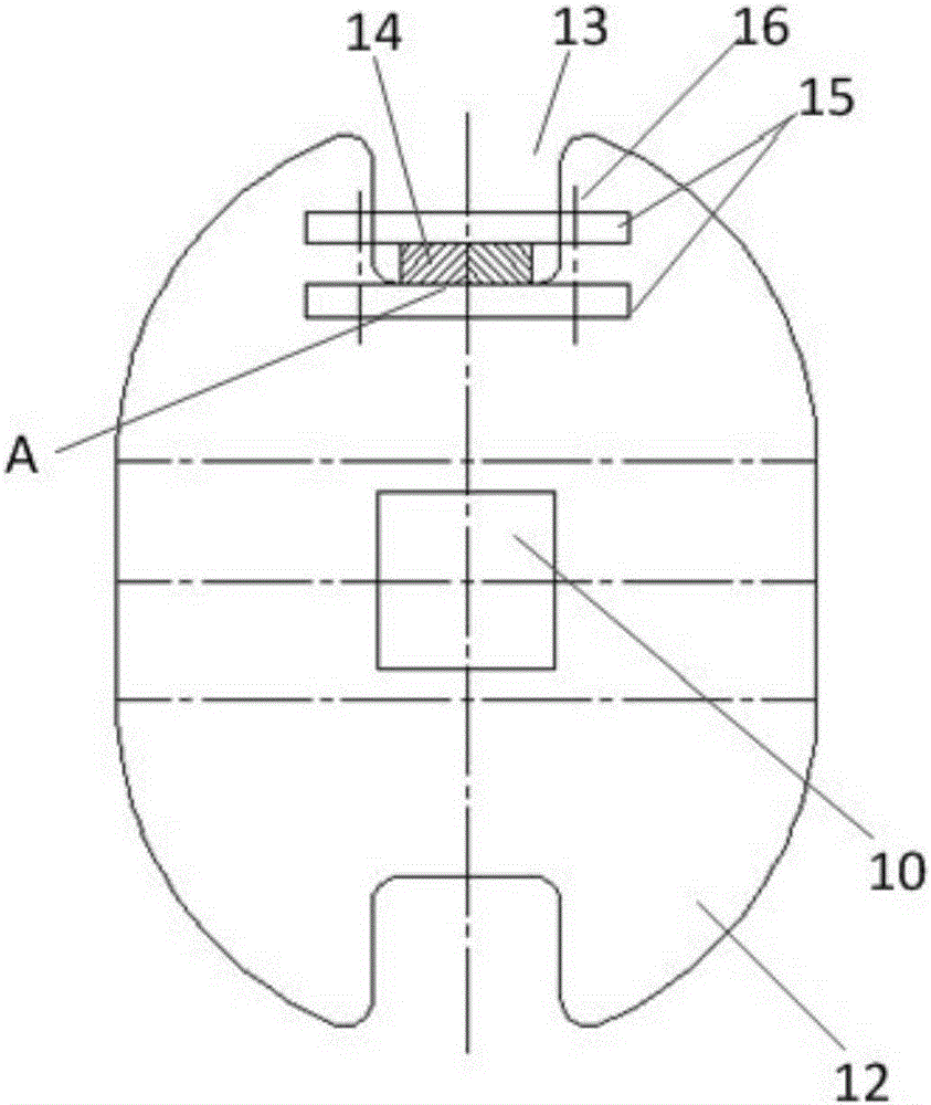
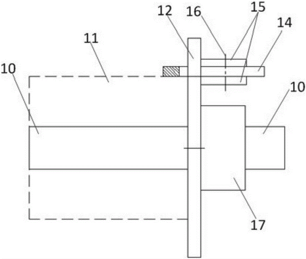
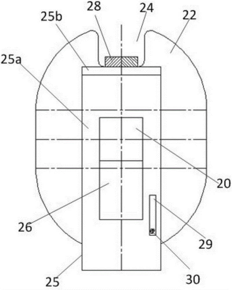
[0016] Such as Figure 3-6 As shown, the present invention provides a transformer low-voltage coil winding tool, including a low-voltage winding die 21 sleeved on the winding machine shaft 20, one end of the low-voltage winding die 21 is provided with a baffle 22, the baffle The center of the plate 22 is provided with a through hole 23, and is installed on the winding machine shaft 20 through the through hole 23. The edge position of the baffle 22 is provided with a baffle gap 24 for the low-voltage coil outlet 28 to lead out, which also includes :

[0017] A positioning plate 25 with an inverted L-shaped longitudinal section is located outside the baffle plate 22. A strip hole 26 is opened in the mi...


PUM


Abstract

The invention discloses a low-voltage coil winding tool for a transformer. The low-voltage coil winding tool for the transformer comprises a low-voltage winding mold arranged on the shaft of a winding machine in a sleeving manner, a positioning plate having an inverse-L-shaped longitudinal section, and a clamping piece, wherein a baffle is arranged at one end of the low-voltage winding mold; a through hole is formed in the center of the baffle; the baffle is arranged on the shaft of the winding machine by the through hole; a baffle gap from which the head of a low-voltage coil can be led out is formed in the edge of the baffle; the positioning plate is arranged at the outer side of the baffle; a strip-shaped hole is formed in the middle of the vertical end of the positioning plate; the positioning plate is arranged on the shaft of the winding machine in a penetrating manner by the strip-shaped hole; the positioning plate can move upwards relative to the shaft of the winding machine by the strip-shaped hole, so that the horizontal end of the positioning plate can be lifted up relative to the baffle gap; the positioning plate and the baffle are connected in a dismountable manner; the clamping piece is used for clamping the positioning plate and the low-voltage coil when the horizontal end of the positioning plate is supported on the head of the low-voltage coil. The low-voltage coil winding tool has the universality and can be suitable for winding of low-voltage coils of transformers with different capacities.

Description

technical field [0001] The invention belongs to the technical field of transformers, in particular to a transformer low-voltage coil winding tool. Background technique [0002] In dry-type transformers or oil-immersed transformers, when the low-voltage coil is a layered coil, it is usually necessary to press the head end on a baffle when winding. Such as Figure 1-2 As shown, the traditional low-voltage coil winding tooling includes a winding machine shaft 10, a low-voltage winding mold 11 is arranged on the winding machine shaft 10, and a baffle 12 is arranged on one side of the low-voltage winding mold 11. The baffle 12 Sleeved on the winding machine shaft 10, the upper edge of the baffle 12 is provided with a baffle notch 13, and the head end 14 of the low-voltage coil protrudes from the notch 13, and is arranged on two fixed blocks outside the baffle 12 15 is clamped with bolts 16, wherein the fixed block 15 positioned at the lower end is fixed and non-adjustable. The ...

Claims


Application Information

Patent Timeline
Patent Type & Authority Applications(China)
IPC IPC(8): H01F41/071H01F41/082
Inventor 张勇周安根
Owner 重庆吉能变压器有限公司
Why Eureka
Try Eureka