Motor stator fixture

A motor stator and fixture technology, applied in the field of tooling and fixtures, can solve the problems of motor stator pressure deformation, poor applicability, and low precision, and achieve the effects of avoiding damage and deformation, easy operation, and improving efficiency

Inactive Publication Date: 2016-02-24
CHANGZHOU XIXIASHU ENTERPRISE INNOVATION DEV CENT
View PDF9 Cites 13 Cited by
  • Summary
  • Abstract
  • Description
  • Claims
  • Application Information

AI Technical Summary

Problems solved by technology

[0002] The motor stator needs to be fixed on the wire embedding machine when the coil is embedded, and the pre-wound coil is embedded into the motor stator with the wire embedding mold. When the motor stator is small, the embedded coil is small, and the force when embedding the wire is small. When the stator is large, the clamping of the motor stator is a big problem. For larger motor stators, a horizontal wire insertion machine is generally used to insert the wires. The motor stator needs to be placed horizontally for clamping. The existing clamps are generally clam

Method used


Image

  • Motor stator fixture
  • Motor stator fixture

Examples


Embodiment 1

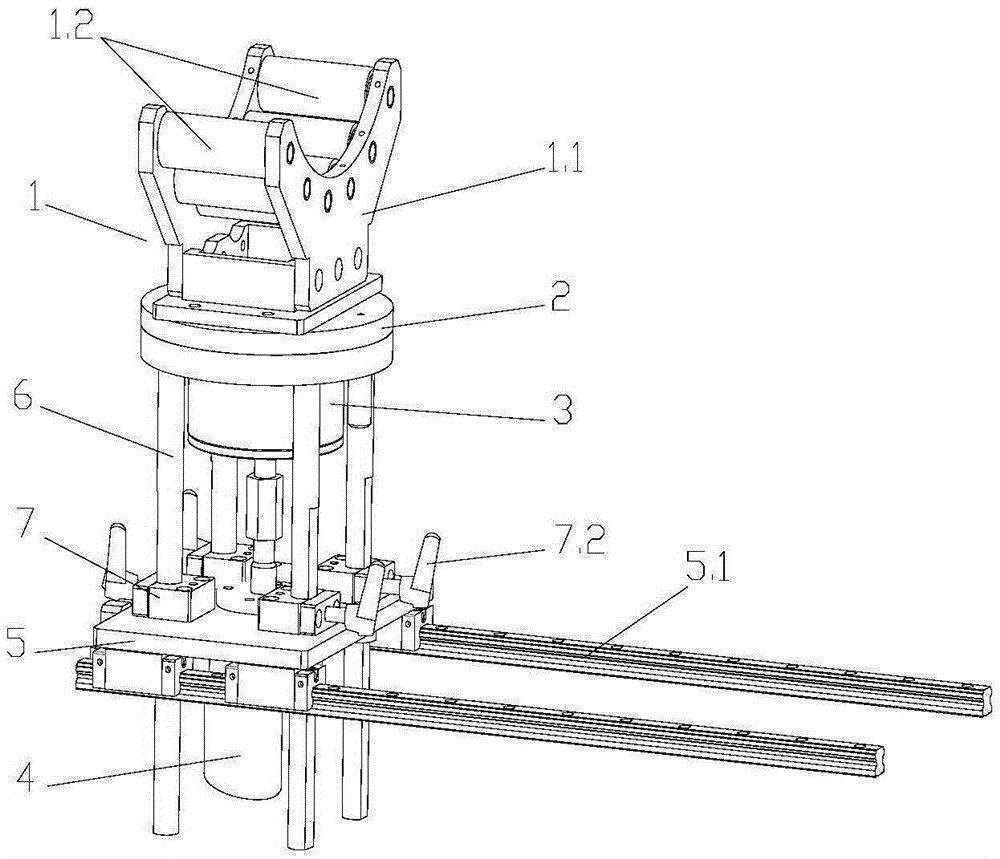
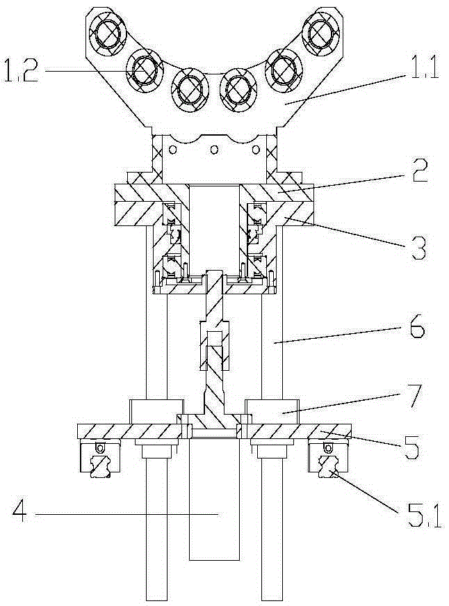
[0014] Embodiment 1: as figure 1 , figure 2 A motor stator fixture shown includes a stator bracket 1 and a rotating seat 2 at the bottom of the stator bracket 1. The bottom of the rotating seat 2 is provided with a bracket seat 3 that is rotatably connected to the rotating seat 2. The bracket seat 3 is sleeved On the protrusion of the shaft center of the bottom surface of the rotating base 2, a bearing connected between the protrusion and the bracket base 3 is provided, and evenly distributed positioning holes are arranged on the rotating base 2 and the bracket base 3, and the rotating base 1 is provided with There are locating pins that are movably connected, and the rotating seat 2 can adjust the angle to be positioned by the locating pins. The stator bracket 1 is composed of two opposite supporting plates 1.1 and a plurality of magnetic rollers 1.2 between the supporting plates 1.1. The plurality of magnetic rollers 1.2 are Arranged in an arc, and the upper part of the su...

Embodiment 2

[0015] Embodiment 2: as figure 1 , figure 2 A motor stator fixture shown includes a stator bracket 1 and a rotating seat 2 at the bottom of the stator bracket 1. The bottom of the rotating seat 2 is provided with a bracket seat 3 that is rotatably connected to the rotating seat 2. The bracket seat 3 is sleeved On the protrusion of the shaft center of the bottom surface of the rotating base 2, a bearing connected between the protrusion and the bracket base 3 is provided, and evenly distributed positioning holes are arranged on the rotating base 2 and the bracket base 3, and the rotating base 1 is provided with There are locating pins that are movably connected, and the rotating seat 2 can adjust the angle to be positioned by the locating pins. The stator bracket 1 is composed of two opposite supporting plates 1.1 and a plurality of magnetic rollers 1.2 between the supporting plates 1.1. The plurality of magnetic rollers 1.2 are Arranged in an arc shape, and the upper part of ...


PUM


Abstract

The present invention belongs to the technical field of tool fixtures and particularly relates to a motor stator fixture which comprises a stator bracket, a rotation seat at the bottom of the stator bracket. The bottom of the rotation seat is provided with a bracket seat which is rotatingly connected to the rotation seat. The bottom of the bracket seat is provided with a driving device which controls the lifting of the bracket seat. The driving device is fixed to the sliding plate of the bottom of the bracket seat. The bottom of the sliding plate is provided with a sliding rail which is matched with the sliding plate. Multiple uniformly distributed lifting support shafts are vertically arranged between the bracket seat and the sliding plate. The sliding plate is provided with locking position machanisms which lock the lifting support shafts corresponding to the lifting support shafts. The stator bracket comprises two opposite support plates, and multiple magnetic rollers are arranged in a curved way between the support plates. The magnetic rollers are provided with wrenches for controlling magnetic force. The structure is simple, the operation difficulty of clamping a motor stator is reduced, the efficiency is improved greatly, the adjustment performance is good, and the adjustment is flexible.

Description

technical field [0001] The invention belongs to the technical field of tooling fixtures, and in particular relates to a motor stator fixture. Background technique [0002] The motor stator needs to be fixed on the wire embedding machine when the coil is embedded, and the pre-wound coil is embedded into the motor stator with the wire embedding mold. When the motor stator is small, the embedded coil is small, and the force when embedding the wire is small. When the stator is large, the clamping of the motor stator is a big problem. For larger motor stators, a horizontal wire insertion machine is generally used to insert the wires. The motor stator needs to be placed horizontally for clamping. The existing clamps are generally clamps. When clamping, it is easy to cause damage to the surface of the motor stator or even deform the motor stator, which greatly affects the production efficiency of the motor stator, and the adjustment of the existing clamps is not good, generally onl...

Claims


Application Information

Patent Timeline
IPC IPC(8): H02K15/06B25B11/02
Inventor 王佳邹春英孙祥龙
Owner CHANGZHOU XIXIASHU ENTERPRISE INNOVATION DEV CENT
Why Eureka
Try Eureka