
Double-fan control cabinet system based on air cooling technology

A control cabinet and dual fan technology, applied in the field of control cabinets, can solve problems such as heat generation

Inactive Publication Date: 2016-02-24
CHONGQING HUAWANLUN ELECTRIC APPLIANCE CO LTD
View PDF0 Cites 0 Cited by
  • Summary
  • Abstract
  • Description
  • Claims
  • Application Information

AI Technical Summary

Problems solved by technology

[0002] The control cabinet is an integrated cabinet that is mostly used in power control, electric control and other fields. It is often designed with a variety of electrical components, but when the electrical components are working, it is inevitable that there will be heat. The accumulated heat dissipates quickly to avoid affecting the control performance of the control cabinet due to long-term poor heat dissipation, which is actually a major breakthrough in the design of the control cabinet

Method used


Image

  • Double-fan control cabinet system based on air cooling technology
  • Double-fan control cabinet system based on air cooling technology

Examples


Embodiment 1

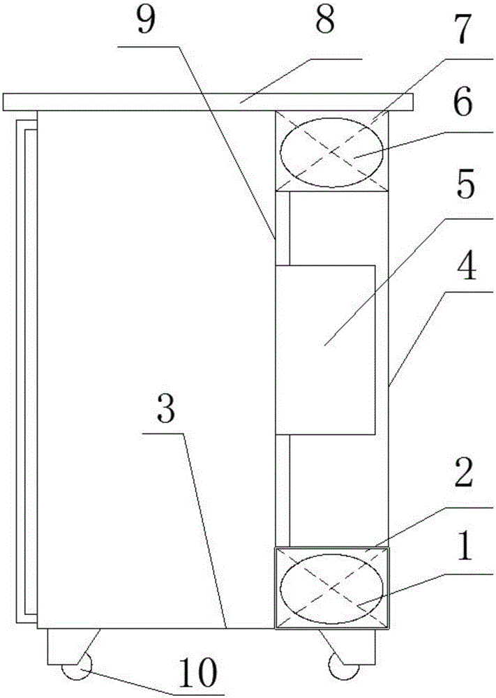
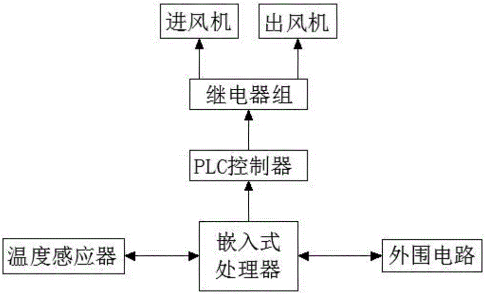
[0021] A control cabinet system with dual fans based on air-cooling technology. A control cabinet system that uses air-cooling technology to effectively dissipate the heat accumulated in the control cabinet is designed. The cold air quickly enters the control cabinet, and the hot air can also be quickly discharged from the control cabinet, so that the control cabinet can continue to work within the normal operating temperature, avoiding the occurrence of control failure; use the temperature sensor to automatically install the electrical components The temperature in the space where the electrical components on the board are located is sensed, and then the power of the inlet fan and the outlet fan is automatically adjusted according to the measured temperature results to achieve the purpose of effective energy saving, such as figure 1 , figure 2 As shown, it is specially set up as the following structure: including the control cabinet and the fan control circuit arranged on th...

Embodiment 2

[0024] This embodiment is further optimized on the basis of the above-mentioned embodiments. In order to better realize the present invention, the two independent spaces in the control cabinet will not affect each other, and the air duct space where the air inlet is located may Incoming dust will not be brought into the space where the front panel of the electrical component installation board is located, affecting the operation of electrical components, such as figure 1 , figure 2 As shown, the following structure is particularly arranged: the four sides of the electrical component mounting plate 9 are respectively sealed and fixedly connected with the inner surfaces of the control cabinet top plate 8, the control cabinet bottom plate 3, the left panel of the control cabinet and the right panel 4 of the control cabinet.

Embodiment 3

[0026] This embodiment is further optimized on the basis of any of the above-mentioned embodiments. Further, in order to better realize the present invention, it can accelerate the heat release from the space where the front panel of the electrical component installation board is located to the air duct space where the rear panel of the electrical component installation board is located. inside, and then release the heat from the air duct space, such as figure 1 As shown, the following structure is particularly provided: the radiator 5 is an aluminum alloy strip, and an exhaust fan is also arranged on the aluminum alloy strip.


PUM


Abstract

The invention discloses a double-fan control cabinet system based on the air cooling technology, comprising a control cabinet and a fan control circuit arranged on the control cabinet. The control cabinet comprises a control cabinet bottom plate, a control cabinet left panel, a control cabinet right panel, a control cabinet rear panel, a control cabinet top plate, and a control cabinet door serving as a front panel. An electrical component installation plate is arranged inside the control cabinet, and the electrical component installation plate divides the control cabinet into independent front and rear spaces. The fan control circuit is internally equipped with an embedded processor, a temperature sensor, a PLC controller, a relay group and a peripheral circuit. The relay group is connected with an air intake fan on an air intake device and an air exhaust fan on an air exhaust device. The temperature sensor automatically senses the temperature in the space where electrical components disposed on the electrical component installation plate are disposed, and then, the power of the air intake fan and the power of the air exhaust fan are adjusted automatically according to the temperature measurement result, thus achieving the goal of effective energy saving.

Description

technical field [0001] The invention relates to the field of control cabinet technology and the like, specifically, a control cabinet system with dual fans based on air-cooling technology. Background technique [0002] The control cabinet is an integrated cabinet that is mostly used in power control, electric control and other fields. It is often designed with a variety of electrical components, but when the electrical components are working, it is inevitable that there will be heat. The heat accumulated inside can be dissipated quickly to avoid affecting the control performance of the control cabinet due to long-term poor heat dissipation, which is actually a major breakthrough point in the design of the control cabinet. Contents of the invention [0003] The purpose of the present invention is to provide a control cabinet system with dual fans based on air-cooling technology, to design a control cabinet system that uses air-cooling technology to effectively dissipate the...

Claims


Application Information

Patent Timeline
Patent Type & Authority Applications(China)
IPC IPC(8): H05K7/20H05K5/02
Inventor 陈洋
Owner CHONGQING HUAWANLUN ELECTRIC APPLIANCE CO LTD
Learn More