Using method for automatic feed tray

An automatic feeding tray and feed technology, which is applied in the field of farming machinery, can solve the problems of reducing feed supply and failing to increase it

Inactive Publication Date: 2016-03-02
重庆市合川区麒麟畜产品有限责任公司
View PDF5 Cites 1 Cited by
  • Summary
  • Abstract
  • Description
  • Claims
  • Application Information

AI Technical Summary

Problems solved by technology

[0003] The disadvantage of using this kind of feeding plate for automatic feeding is that it is necessary to manually adjust the thread matching stroke between the feeding pipe and the height limiting cylinder each time to adjust the distance between the height limiting cylinder an

Method used


Image

  • Using method for automatic feed tray

Examples


Embodiment Construction

[0017] The present invention will be described in further detail below by means of specific embodiments:

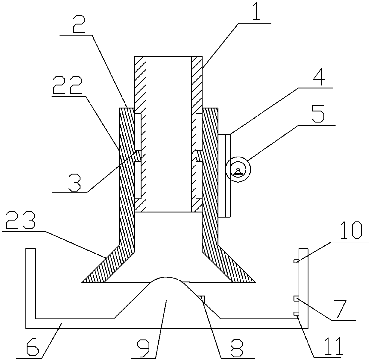
[0018] The reference signs in the accompanying drawings of the specification include: feed pipe 1, height limit cylinder 2, cone cylinder portion 21, straight cylinder portion 22, slider 3, rack 4, driving gear 5, feed trough 6, laser emitter 7 , Laser receiver 8, truncated cone 9, upper travel switch 10, lower travel switch 11.

[0019] This method uses as figure 1 As shown in the automatic feeding tray, if the automatic feeding tray is set on a frame, a screw feeder (not shown in the figure) is arranged on the frame, including a feeding pipe 1, and the upper end of the feeding pipe 1 Connected with the outlet of the screw feeder, the wall of the feed pipe 1 is provided with a vertical guide groove. The outer circle of the feed pipe 1 is covered with a height-limiting cylinder 2, which is divided into a straight cylinder part 22 and a cone cylinder part 21 from top to ...


PUM


Abstract

The present invention discloses a using method for an automatic feed tray. The method comprises the following steps: (1) opening a screw feeder, wherein the screw feeder pushes forage to move toward an orifice of an upper end of a feed pipe; (2) discharging the forage from the upper end of the feed pipe, and entering a trough along a channel between a circular cone and a height-limiting cylinder; (3) after the height of a forage layer is lower than that of a laser emitter/a laser receiver, receiving a laser signal by using the laser receiver and transmitting the signal to a central processing unit; (4) after the central processing unit receives the laser signal, driving a drive gear to rotate counterclockwise by using a rotary electric machine, so that the height-limiting cylinder welded to a rack gear moves upward and stops moving until the height-limiting cylinder touches an upstroke switch; and (5) after the height of the forage layer is higher than that of the laser emitter/the laser receiver, controlling the height-limiting cylinder to move downward by using the central processing unit and stops moving until the height-limiting cylinder touches a downstroke switch. According to the using method for the automatic feed tray, forage replenishment quantity is controlled by adjusting channel width.

Description

technical field [0001] The invention belongs to the technical field of farming machinery. Background technique [0002] The existing factory automation poultry farming adopts automatic feeding. Commonly used automatic feeding equipment includes a feeding pan. This feeding pan includes a vertical feeding pipe. The thread on the feeding pipe is equipped with a height limit cylinder. The outer circle of the feed pipe is fixedly connected with a bracket, and the lower end of the bracket is fixed with a feed trough, which is located under the height limiting cylinder, and the position where the feed trough is opposite to the lower end of the height limiting cylinder protrudes upwards to form a truncated cone. The feed falling in the height limiting cylinder falls onto the feed trough along the conical frustum. [0003] The disadvantage of using this kind of feeding plate for automatic feeding is that it is necessary to manually adjust the thread matching stroke between the feedi...

Claims


Application Information

Patent Timeline
IPC IPC(8): A01K39/012
CPCA01K39/012
Inventor 谭万琦
Owner 重庆市合川区麒麟畜产品有限责任公司
Why Eureka
Try Eureka