
kitchen equipment

A technology for kitchen equipment and lids, which is applied in the field of kitchen equipment and can solve problems such as the inability to detect the locking position of lids

Inactive Publication Date: 2018-05-29
VORWERK & CO INTERHOLDING GMBH
View PDF9 Cites 0 Cited by
  • Summary
  • Abstract
  • Description
  • Claims
  • Application Information

AI Technical Summary

Problems solved by technology

[0005] However, if the lid cannot be completely removed from the container and is not fixed on it by means of a hinge, then the technique described in DE 101 11 437 A1 cannot be used to detect the correct locking position of the lid
In addition, the use of proximity sensors that work on the inductive principle is also problematic in the case of assumptions that other devices as lids can also detect that the lid is in its defined closed position.

Method used


Image

  • kitchen equipment
  • kitchen equipment
  • kitchen equipment

Examples


Embodiment Construction

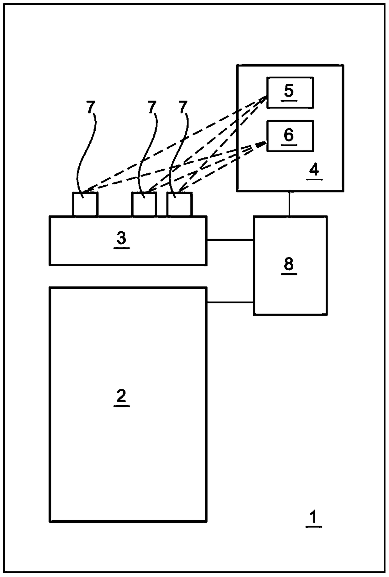
[0030] From figure 1 A kitchen appliance 1 according to a preferred embodiment of the invention can be seen clearly. The kitchen appliance 1 comprises a container 2 with a lid 3 . In order to lock the lid 3 to the container 2, a locking device 8 is provided.

[0031] In order to allow the lid 3 to be locked with the container 2 only when the lid 3 is properly placed on the container 2, the above-mentioned preferred embodiment of the present invention is provided as follows:

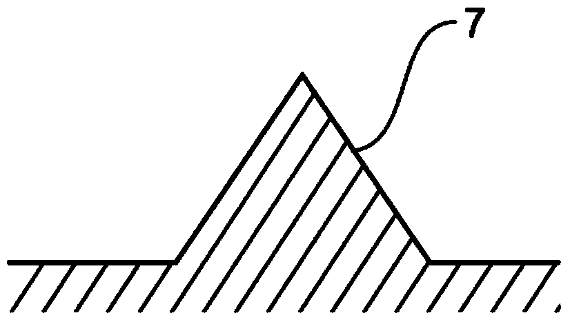
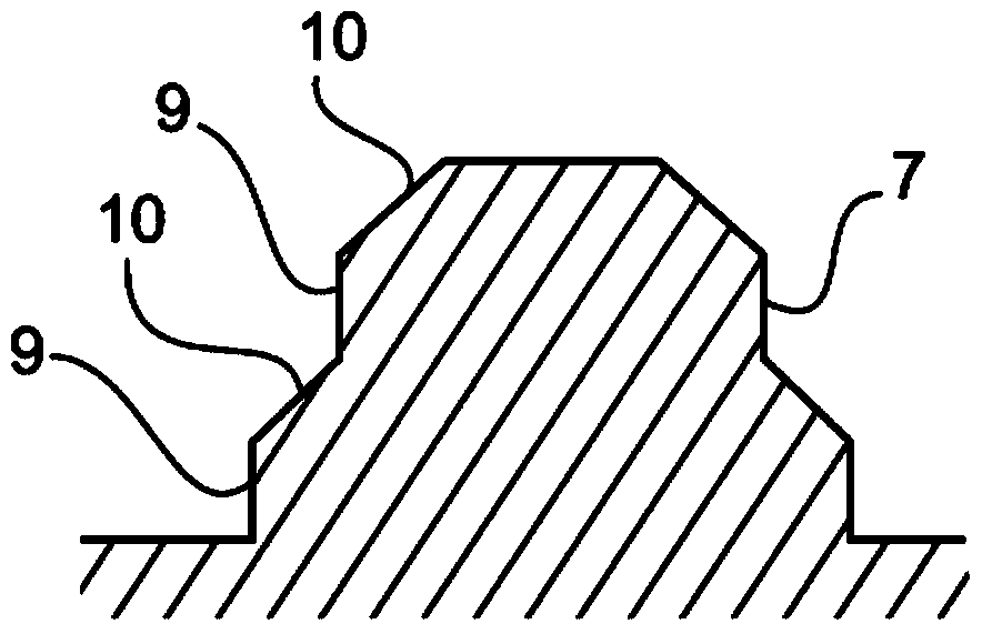
[0032] A control unit 4 , a light source 5 , ie a laser, and a receiving unit 6 , ie an optical receiver in the form of a photodiode, are arranged as constituents in a part of the kitchen appliance 1 other than the container 2 and the lid 3 . The light emitted by the light source 5 is reflected on the identification device 7 provided on the cover 3 , so that the reflected light is reflected into the receiving unit 6 under the condition that the cover 3 is located at a preset position.

[0033] On the c...


PUM


Abstract

The invention relates to a kitchen appliance. The kitchen appliance comprises a container (2) and a lid (3) used for closing the container (2) and is provided with a locking device (8), via which the lid (3) and the container (2) can be locked. The kitchen appliance further comprises a control unit (4), via which the position of the lid (3) can be determined in a non-contact manner. The lid (3) is provided with at least one recognition device (7) and the control unit (4) is provided with at least one receiving unit (6) such that a signal emitted by the recognition device (7) can be received by receiving units (6).The number of recognition devices (7) and receiving devices (6) can be selected, namely, three different devices including recognition devices (7) and the receiving devices can be used in pairs. The lid (3) can be locked on the container (2) in a universal manner at the specified position.

Description

technical field [0001] The invention relates to a kitchen appliance, comprising a container and a cover for closing the container, wherein a locking device is provided, by which the cover can be locked with the container, and a control unit, by which the cover can be locked without contact The position of the cover is determined formulaically, wherein the cover has at least one identification device and the control unit is provided with at least one receiving unit, so that the signal emitted by the identification device can be received by the receiving unit. Background technique [0002] Such kitchen appliances with containers and lids for closing them are known in practice. Examples include pressure cookers and multifunction food processors. The latter are usually provided with a container which can accommodate ingredients so that they can be processed in the container. The processing of such foodstuffs can be, for example, crushing, stirring or kneading. In addition to ...

Claims


Application Information

Patent Timeline
Patent Type & Authority Patents(China)
IPC IPC(8): A47J36/10A47J27/08
CPCA47J43/0772
Inventor 托尔斯滕·朗格奥尔格·哈克特尤塔·朔马赫斯塔凡·克劳特-赖因科贝尔安德烈斯·索尔沃德
Owner VORWERK & CO INTERHOLDING GMBH
Learn More