A grinding mechanism for automatic grinding and cleaning machine of crankshaft

A cleaning machine and grinding technology, which is applied to the parts of grinding machine tools, machine tools designed for grinding the rotating surface of workpieces, grinding drive devices, etc., can solve the problems of low automation and work efficiency, poor quality of polished products, and workpiece Easy to jam and other problems, achieve good practical effect, improve the quality of grinding products, and compact equipment structure

Active Publication Date: 2017-05-24
AUTOMOTIVE ENG CORP +1
View PDF5 Cites 0 Cited by
  • Summary
  • Abstract
  • Description
  • Claims
  • Application Information

AI Technical Summary

Problems solved by technology

[0004] The technical purpose of the present invention is to provide a grinding mechanism for an automatic crankshaft grinding and cleaning machine, to solve the problem that the crankshaft grinding device in the prior art has poor adaptability to models of different sizes, the workpiece is easily stuck during grinding, and the failure rate is high. Low degree of automation and work efficiency, poor quality of workpiece grinding and other technical problems

Method used


Image

  • A grinding mechanism for automatic grinding and cleaning machine of crankshaft
  • A grinding mechanism for automatic grinding and cleaning machine of crankshaft
  • A grinding mechanism for automatic grinding and cleaning machine of crankshaft

Examples


specific Embodiment approach

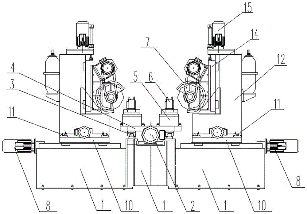
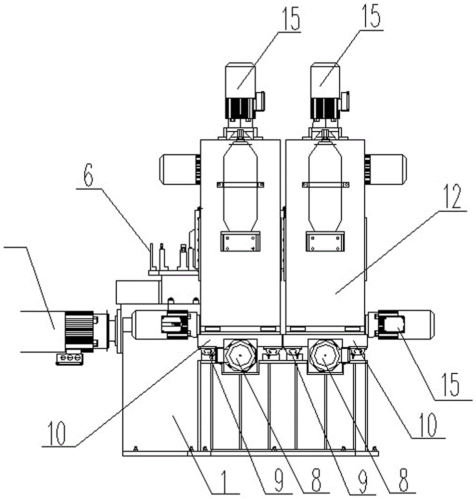
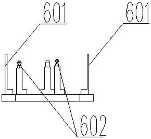
[0030] A grinding mechanism for an automatic crankshaft grinding and cleaning machine, the grinding mechanism includes a horizontally arranged bed 1, a workbench arranged on the bed 1, a workpiece feeding device 2, and multiple sets of grinding wheel assemblies. The workbench consists of a linear guide rail I3 installed on the bed 1, a slide table 4 that can move back and forth along the linear guide rail I3 driven by the workpiece feeding device 2, and a plurality of workpiece CNC rotary tables 5 set on the slide table 4 , the top of each workpiece CNC rotary table 5 is provided with a set of workpiece fixtures 6 for supporting a crankshaft to be ground, and corresponding to the top of each workpiece CNC rotary table 5 is also provided with a set for pressing the crankshaft to be ground The workpiece clamping device, the axial direction of the crankshaft supported on the workpiece fixture 6 is consistent with the direction in which the slide table 4 moves back and forth along ...


PUM


Abstract

A grinding mechanism for an automatic crank shaft polishing and cleaning machine comprises a lathe bed, a working table, a workpiece feeding device and a plurality of grinding wheel assemblies, wherein each grinding wheel assembly comprises a grinding wheel, a grinding wheel adjusting rack and a grinding wheel feeding device; each grinding wheel adjusting rack and the corresponding grinding wheel feeding device can be matched with each other; each grinding wheel assembly is used for machining a corresponding workpiece to be ground; the grinding wheels in the grinding mechanism can be in linkage in the X, Y and Z directions in an adjusting moving process of three linear tracks; crank shaft workpieces move on a main X axis along with stroke of a sliding table; and through four-axis linkage, the workpieces with different sizes can be ground at various angles along curves of parting faces of the crank shafts. According to the grinding mechanism disclosed by the invention, the four grinding assemblies work simultaneously, four crank shaft workpieces can be simultaneously machined at a time, and through a plurality of device components which are matched with one another, the crank shaft workpieces are ground and cleaned fully automatically, manual assistance is not required in a grinding process, production efficiency is improved, and labor intensity is reduced.

Description

technical field [0001] The invention relates to the technical field of crankshaft grinding and cleaning equipment, in particular to a grinding mechanism for an automatic crankshaft grinding and cleaning machine. Background technique [0002] At present, the crankshaft grinding and cleaning equipment in the prior art mainly has the following major problems: 1. The grinding head used in the grinding process of the existing crankshaft grinding machine can only move up and down or forward and backward. There is no way to adapt to the dimensional changes caused by different models. Cause the utilization rate of crankshaft grinding and cleaning equipment to be low. 2. The existing crankshaft grinder generally can only process one or two crankshafts at a time, and the work efficiency is low. If multiple devices are used, the floor space will be too large. Can not meet the production requirements of production. 3. The existing crankshaft grinding machine uses a spring structure t...

Claims


Application Information

Patent Timeline
Patent Type & Authority Patents(China)
IPC IPC(8): B24B5/42B24B27/00B24B47/20
CPCB24B5/42B24B5/421B24B27/0023B24B47/20
Inventor 马颖李百强刘洪纬刘小龙卫洪赵瑛时哲张佳夫李明田浩
Owner AUTOMOTIVE ENG CORP
Why Eureka
Try Eureka