Automatic crank shaft grinding and cleaning machine

A technology for cleaning machines and crankshafts, which is applied in the direction of grinding racks, grinding machine parts, grinding machines, etc. It can solve the problems of low automation and work efficiency, poor quality of workpiece grinding products, and high failure rate of crankshaft grinding machines. Good practical effect, improve the quality of grinding products, and good transfer effect

Active Publication Date: 2016-03-02
AUTOMOTIVE ENG CORP +1
View PDF8 Cites 11 Cited by
  • Summary
  • Abstract
  • Description
  • Claims
  • Application Information

AI Technical Summary

Problems solved by technology

[0004] The technical purpose of the present invention is to provide an automatic grinding and cleaning machine for crankshafts, which solves the technical problems of high failure rate, low automation and work efficiency, poor quality of finished workpiece grinding, and unreasonable equipment layout in the prior art.

Method used


Image

  • Automatic crank shaft grinding and cleaning machine
  • Automatic crank shaft grinding and cleaning machine
  • Automatic crank shaft grinding and cleaning machine

Examples


specific Embodiment approach

[0043] The crankshaft automatic grinding and cleaning machine includes a frame 1 and a feeding device 2, a workpiece transfer device 3, a grinding mechanism 4 and a discharge device 5 arranged on the frame 1. The workpiece transfer device 3 is erected through a support column 6 Above the frame 1 , the crankshaft to be ground conveyed by the feeding device 2 is conveyed to the grinding mechanism 4 for grinding, and then the crankshaft is conveyed to the discharging device 5 for output.

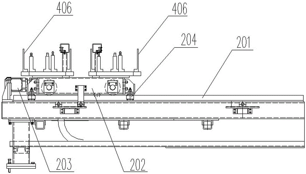
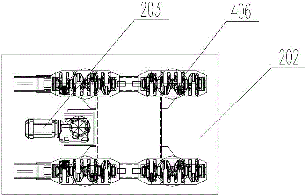
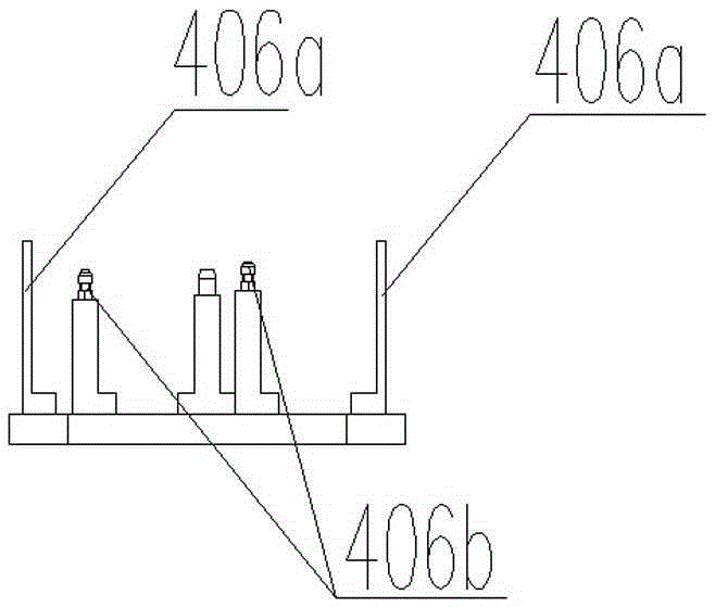
[0044] The feeding device 2 or the discharging device 5 includes a working platform 201, a material transporting trolley 202 and a first drive motor 203, and the first driving motor 203 drives the material transporting trolley 202 on the working platform 201 through a rack and pinion. To carry out the material transporting operation, the top of the material transporting trolley 202 is provided with four sets of workpiece fixtures 406 for supporting the four crankshafts to be transported respecti...


PUM


Abstract

An automatic crank shaft grinding and cleaning machine comprises a rack, a feeding device, a workpiece transfer device, a grinding mechanism and a discharging device, wherein the feeding device, the workpiece transfer device, the grinding mechanism and the discharging device are arranged on the rack; and the workpiece transfer device is erected above the rack through a supporting upright column, and is used for conveying to-be-ground crank shafts conveyed by the feeding device into the grinding mechanism to be ground, and conveying the crank shafts to the discharging device so as to discharge the crank shafts after the crank shafts are ground. According to the automatic crank shaft grinding and cleaning machine, workpieces are fed and discharged by a robot, four crank shaft workpieces can be simultaneously machined at a time, and through a plurality of device components which are matched with one another, the crank shaft workpieces can be ground and cleaned fully automatically, production efficiency is improved, human resources are saved, and labor intensity of operators is also reduced. By the grinding mechanism, linkage of grinding wheels in the X, Y and Z directions can be realized, the crank shaft workpieces move on a main X axis along with the stroke of a sliding table, and through four-axis linkage, the workpieces with different sizes can be ground at various angles along curves of parting faces of the crank shafts.

Description

technical field [0001] The invention relates to the technical field of crankshaft grinding and cleaning equipment, in particular to an automatic crankshaft grinding and cleaning machine. Background technique [0002] At present, the existing crankshaft grinding and cleaning equipment mainly has the following major problems: 1. Most of the existing crankshaft grinding machines are manual upper and lower parts, and the degree of automation is low, which takes up a lot of human resources. 2. The grinding head used in the grinding process can only move up and down or back and forth, and there is no way to adapt to the dimensional changes of the crankshaft castings to be ground due to different models. As a result, the utilization rate of crankshaft grinding and cleaning equipment is low. 3. The existing crankshaft grinding machine can generally only complete one or two crankshaft processing at a time, and the work efficiency is low. If multiple sets of equipment are selected,...

Claims


Application Information

Patent Timeline
Patent Type & Authority Applications(China)
IPC IPC(8): B24B5/42B24B5/35B24B27/00B24B41/06B24B55/00B24B47/12B24B47/20B24B41/02
CPCB24B5/355B24B5/42B24B27/0076B24B41/02B24B41/067B24B47/12B24B47/20B24B55/00
Inventor 马颖李百强刘洪纬刘小龙卫洪赵瑛时哲张佳夫李明田浩
Owner AUTOMOTIVE ENG CORP
Why Eureka
Try Eureka