
Balance hanger for motor rotor

A technology for balancing spreaders and motor rotors, which is applied in the direction of load hanging components, transportation and packaging, etc., which can solve the problems that the rotor balance cannot be fine-tuned or fine-tuned, and the operation is not flexible enough, etc., so as to facilitate serialization and mass production , Reduce labor intensity, overcome the effect of cumbersome operation

Inactive Publication Date: 2016-03-02
襄阳中车电机技术有限公司
View PDF0 Cites 2 Cited by
  • Summary
  • Abstract
  • Description
  • Claims
  • Application Information

AI Technical Summary

Problems solved by technology

[0002] At present, the motor rotor sling known or used by the motor factory all adopts the wire rope to pass through the lifting hole on the L-shaped boom to lift the motor rotor. Therefore, the general rotor sling has the following disadvantages: (1) The rotor balance cannot be fine-tuned or fine-tuned, and finally needs to be manually assisted to balance; (2) When adjusting the rotor level, it is necessary to pull through the wire rope many times, and the operation is not flexible enough.

Method used


Image

  • Balance hanger for motor rotor
  • Balance hanger for motor rotor
  • Balance hanger for motor rotor

Examples


Embodiment Construction

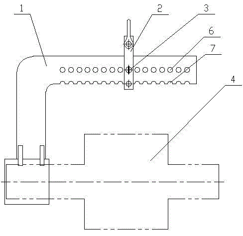
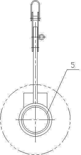
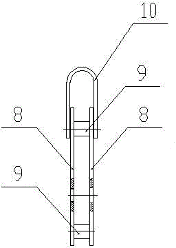
[0013] Such as figure 1 , 2 , 3, the motor rotor balance hanger of the present invention comprises an L-shaped boom 1, a suspension hook 2, pins 3 and copper sleeves 5; a row of pinholes 6 is evenly arranged on a right-angled arm of the L-shaped boom 1, L A row of semicircular grooves 7 are evenly opened on the lower edge of the right-angle arm of the L-shaped boom 1; the hook 2 is fixed on the pin hole 6 on the L-shaped boom 1 through a pin 3, and the hook 2 can be adjusted to be fixed on the L-shaped boom 1 as required. The horizontal position on the boom 1, and the position of the hook 2 is fixed by the pin 3; the hook 2 is composed of two splints 8, two pins 9, and a U-shaped hook 10, two splints 8 parallel Connected by two column pins 9 up and down, a U-shaped hook 10 is connected on two splints 8 through the upper column pin 9, and connected to the semicircular groove 7 on the lower edge of the right-angle arm of the L-shaped boom 1 through the lower column pin 9 Above...


PUM


Abstract

The invention discloses a balance hanger for a motor rotor and particularly relates to a balance hanger for a motor rotor. The balance hanger mainly aims to solve the problems that general rotor hangers sling motor rotors by adopting a mode that lifting holes in L-shaped lifting arms are threaded with steel wire ropes, fine control or fine tuning for balance of the rotors cannot be achieved, manual assisting balance is required, and when the rotors are adjusted to be horizontal, the steel wire ropes need to be threaded and pulled out for a plurality of times, the operation is inflexible and troublesome, and the production efficiency is low. According to the balance hanger, a right-angled arm of an L-shaped lifting arm is provided with a row of uniformly aligned pin holes, a hanging hook is fixed in one of the pin hole of the L-shaped lifting arm through a pin, and a copper bush is fixed to the end of the other right-angled arm of the L-shaped lifting arm. When the balance hanger is used for lifting, the horizontal position of the motor rotor can be guaranteed by using a crown block to sling the hanging hook, and horizontal lifting of the motor rotor can be achieved under the condition that threading and pulling out of a steel wire rope and manual assisting balance are not needed. The balance hanger is simple in structure, simple and convenient to operate, efficient, and suitable for serialization and batch production of motors.

Description

technical field [0001] The invention relates to a motor rotor sling, in particular to a motor rotor balance sling. Background technique [0002] At present, the motor rotor sling known or used by the motor factory all adopts the wire rope to pass through the lifting hole on the L-shaped boom to lift the motor rotor. Therefore, the general rotor sling has the following disadvantages: (1) The rotor balance cannot be fine-tuned or fine-tuned, and finally manual assistance is required for balancing; (2) When adjusting the rotor level, it is necessary to pull through the wire rope many times, and the operation is not flexible enough. Contents of the invention [0003] The object of the present invention is to overcome the above disadvantages and provide a motor rotor balancing sling with simple structure, flexible operation and high efficiency. [0004] The technical solution of the present invention is: a row of pin holes is evenly arranged on one right-angled arm of the L-sh...

Claims


Application Information

Patent Timeline
IPC IPC(8): B66C1/10
Inventor 黄锋
Owner 襄阳中车电机技术有限公司
Learn More