Supercharge Your Innovation With Domain-Expert AI Agents!

Direct drive drawworks with bearingless motor

A direct, motor technology, applied in the field of electric motor installation, which can solve problems such as failure

Inactive Publication Date: 2016-03-02
NABORS DRILLING TECH USA INC
View PDF3 Cites 0 Cited by
  • Summary
  • Abstract
  • Description
  • Claims
  • Application Information

AI Technical Summary

Problems solved by technology

Any movement due to misalignment or bearing play can be inhibited by fixed mounting to the surface which can cause stress in the shaft, bearing and surface mount which can cause premature fatigue and possibly failure

Method used


Image

  • Direct drive drawworks with bearingless motor
  • Direct drive drawworks with bearingless motor
  • Direct drive drawworks with bearingless motor

Examples


Embodiment Construction

[0016] It should be understood that the following disclosure provides many different embodiments or examples for implementing different features of various embodiments. Specific examples of components and arrangements are described below to simplify the present disclosure. Of course, these are merely exemplary and are not intended to be limiting. In addition, the present invention may repeat reference numerals and / or letters in various examples. This repetition is for simplicity and clarity and does not in itself indicate a relationship between the various embodiments and / or configurations discussed.

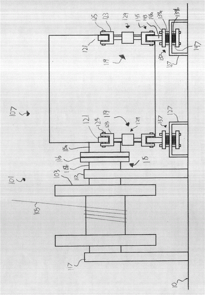
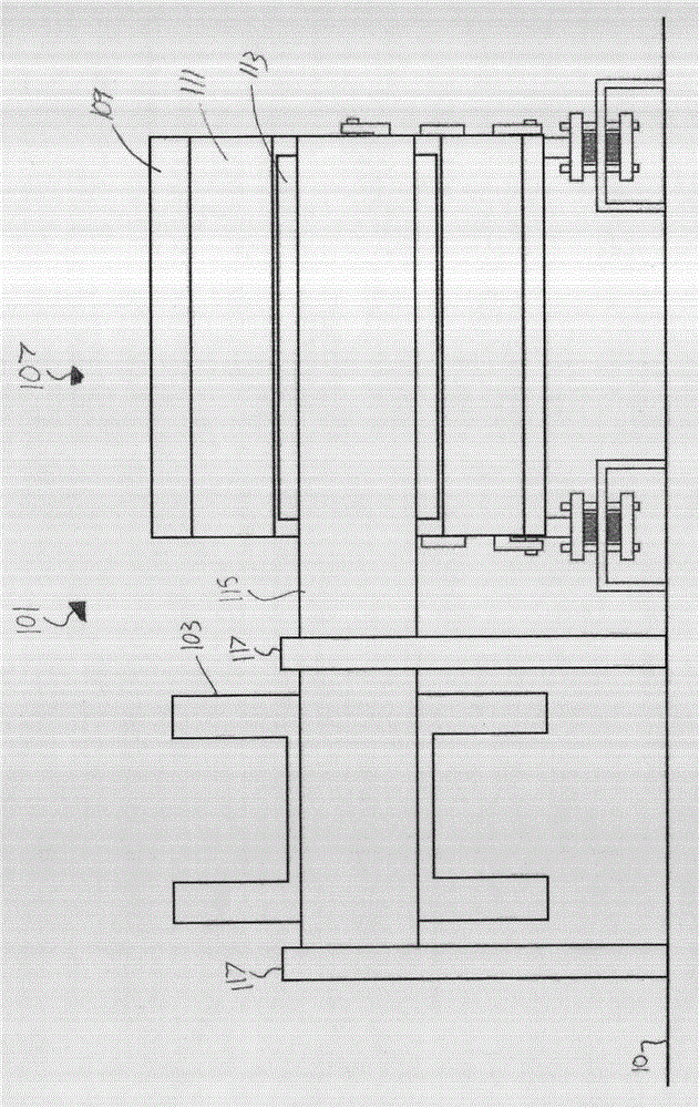
[0017] figure 1 , 2 A winch 101 consistent with an embodiment of the invention is illustrated. A winch 101 is positioned on the surface 10 . In some embodiments, surface 10 may be, for example and without limitation, the deck of a drilling rig for which winch 101 is used. In other embodiments, the surface 10 may be an underframe, frame, or skid on which the winch 101 is p...


PUM


Abstract

An electric motor for a direct drive drawworks may be supported by one or more motor mounts. The motor mounts may include adjusting assemblies adapted to increase or decrease the length of the motor mounts. The motor mounts may include damping assemblies adapted to allow damped motion between the electric motor and the surface. The length and damping coefficients of the motor mounts may be adjusted to align the electric motor with the drum or shaft to reduce vibration. The electric motor may be removable from the drawworks by, for example, a splined shaft, a flange coupled shaft, or the rotor being selectively removable from the interior of the motor.

Description

technical field [0001] The present invention relates generally to the mounting of electric motors, and in particular to motor mounts for drawworks, mining hoists, winches or mud pumps. Background technique [0002] In equipment driven by electric motors, misalignment between its rotating parts and the electric motor or stacking of deviations in bearing clearances can lead to undesired results including vibration, noise, or damage to the motor or equipment. In addition, the reaction torque induced by the drive shaft can lead to undesired vibrations or unexpected internal disturbances in the motor. For example, if the stator experiences undesired rotational vibration, the electric motor can "cog", resulting in excessive noise and jerk. [0003] For example, a drawworks is a common piece of oilfield equipment used in oil and gas drilling and production. A winch is positioned to raise and lower the traveling block in the drilling rig. The traveling block is suspended from the...

Claims


Application Information

Patent Timeline
Patent Type & Authority Applications(China)
IPC IPC(8): B66D1/12B66D1/28H02K5/26H02K5/24
CPCH02K5/24H02K5/26H02K7/14B66D1/14F16M7/00F16F15/04F16M1/04B66D1/12B66D1/82
Inventor 比特·库特尔费萨尔·优素福凯文·R·威廉姆斯布莱恩·埃利斯
Owner NABORS DRILLING TECH USA INC
Features
  • R&D
  • Intellectual Property
  • Life Sciences
  • Materials
  • Tech Scout
  • Unparalleled Data Quality
  • Higher Quality Content
  • 60% Fewer Hallucinations
Learn More