Vehicle hydraulic damper with actively adjustable damping for semiactive suspension

A hydraulic shock absorber, semi-active technology, applied in the field of hydraulic shock absorbers, can solve the problems of rotor valve impact, damping force discontinuity, etc., and achieve the effect of reliable operation, strong anti-pollution ability and simple structure

Inactive Publication Date: 2005-11-23
ZHEJIANG UNIV
View PDF0 Cites 32 Cited by
  • Summary
  • Abstract
  • Description
  • Claims
  • Application Information

AI Technical Summary

Problems solved by technology

For this type of shock absorber with step-by-step damping adjustment, the position of the rotor valve cha...

Method used


Image

  • Vehicle hydraulic damper with actively adjustable damping for semiactive suspension
  • Vehicle hydraulic damper with actively adjustable damping for semiactive suspension
  • Vehicle hydraulic damper with actively adjustable damping for semiactive suspension

Examples


Embodiment Construction

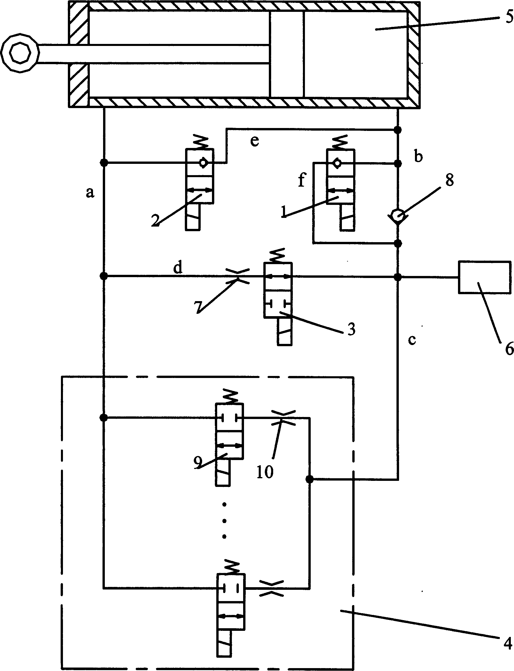
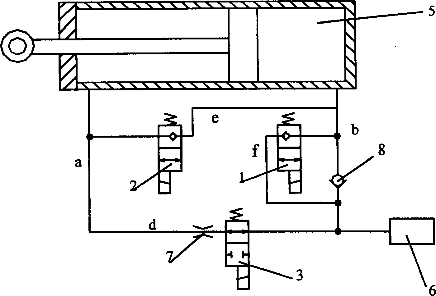
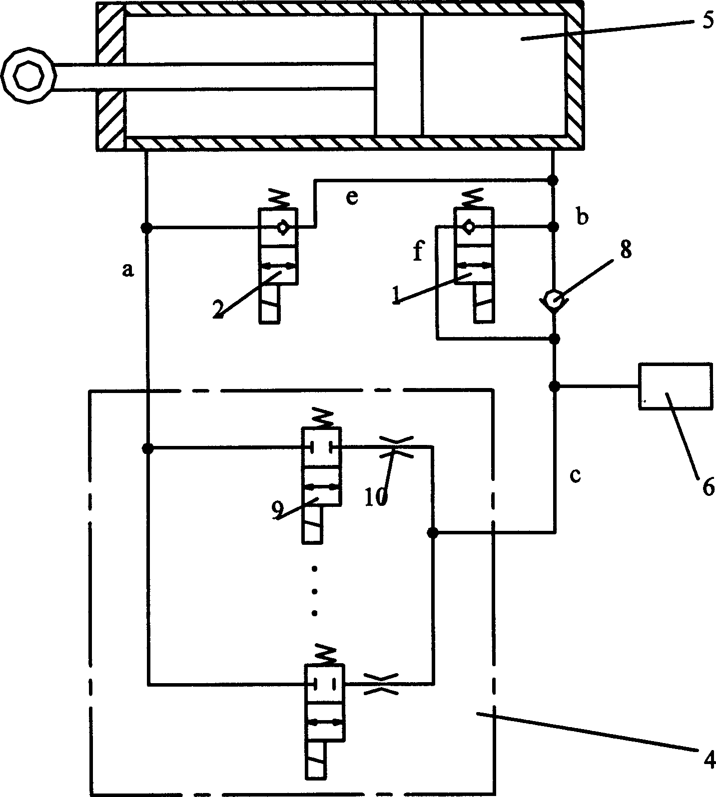
[0014] Such as figure 1 As shown, the hydraulic shock absorber with actively adjustable damping for vehicle semi-active suspension includes a damping control unit composed of a plurality of high-speed electromagnetic switch valves 9 connected in series with fixed dampers 10 and connected in parallel to form a hydraulically adjustable damping control valve 4. One end of the damping control valve 4 connects with the oil storage tank 6, one end of the third electromagnetic valve 3, and one end of the check valve 8 through the oil circuit c, and then connects with the end of the first electromagnetic valve 1 and the right chamber of the damping cylinder 5 through the oil circuit b , the other end of the first electromagnetic valve 1 is connected to the oil circuit c through the oil circuit f, the other end of the hydraulic adjustable damping control valve 4 is connected to the fixed damper 7 through the oil circuit a, the second electromagnetic valve 2 is connected to the left side...


PUM


Abstract

The invention discloses a liquid control valve with adjustable damp which comprises: a damping control unit that is constructed by high speed electro-magnetism switch valve and fixing damp connected in row, several damp control units joint in parallel forms the liquid damper control valve with adjustable damp, one of its end oil line is connected with the right chamber of the damping vibration cylinder via the oil tank, one end of the third electro-magnetism valve, one end of single direction valve and oil line b; the other end of the first electro-magnetism valve is connected with oil line c via the oil line f; the other end of the liquid control valve with adjustable damp is connected with one end of the fixing damp, one end of the second electro-magnetism valve, the left chamber of the damping vibration cylinder via oil line a; the other end of the fixing damper is connected with the other end of the third electro-magnetism valve and the other end of the second electro-magnetism valve is connected with oil b via oil e. The invention can get the corresponding damp coefficient with the different requirement of the system.

Description

Technical field [0001] The invention relates to a vehicle suspension system, in particular to a hydraulic shock absorber with actively adjustable damping for semi-active suspension of a vehicle. Background technique [0002] Vehicle suspension systems are divided into three types: passive suspension, active suspension and semi-active suspension. With the development of high-speed trains, passive suspension has been eliminated in foreign countries. my country's trains are developing towards high-speed trains. Active and semi-active suspensions are the development trend of train suspension systems. Semi-active suspension system vibration control was proposed by Karnopp et al. in 1973. This form of suspension system mainly adjusts damping by inputting a small amount of control energy to improve vehicle vibration characteristics. Then Margolis et al. proposed the on-off semi-active control strategy in 1975, which is characterized in that when the suspended mass and the non-susp...

Claims


Application Information

Patent Timeline
IPC IPC(8): F16F9/50
Inventor 刘荣王宣银
Owner ZHEJIANG UNIV
Why Eureka
Try Eureka