Spring, cam and torsion bar type constant force mechanism

A cam mechanism and torsion bar technology, applied in the field of passive adaptive constant force loading mechanism, can solve problems such as difficulty in adapting to various tasks, failure to achieve large torque output, low torque value, etc., and achieve easy constant force feedback closed-loop control , small inertia and adjustable torque

Inactive Publication Date: 2016-03-02
HARBIN INST OF TECH
View PDF6 Cites 0 Cited by
  • Summary
  • Abstract
  • Description
  • Claims
  • Application Information

AI Technical Summary

Problems solved by technology

[0004] The present invention solves the problem that the output torque of the existing passive constant force output device is a gradual torque, and the torque value changes linearly with the change of the rotation angle, and the torque value is low, so that the output of large torque cannot be realized, and it is difficult to adapt to the needs of various tasks. problem, and then provide a spring cam torsion bar type constant force mechanism

Method used


Image

  • Spring, cam and torsion bar type constant force mechanism
  • Spring, cam and torsion bar type constant force mechanism

Examples


specific Embodiment approach 1

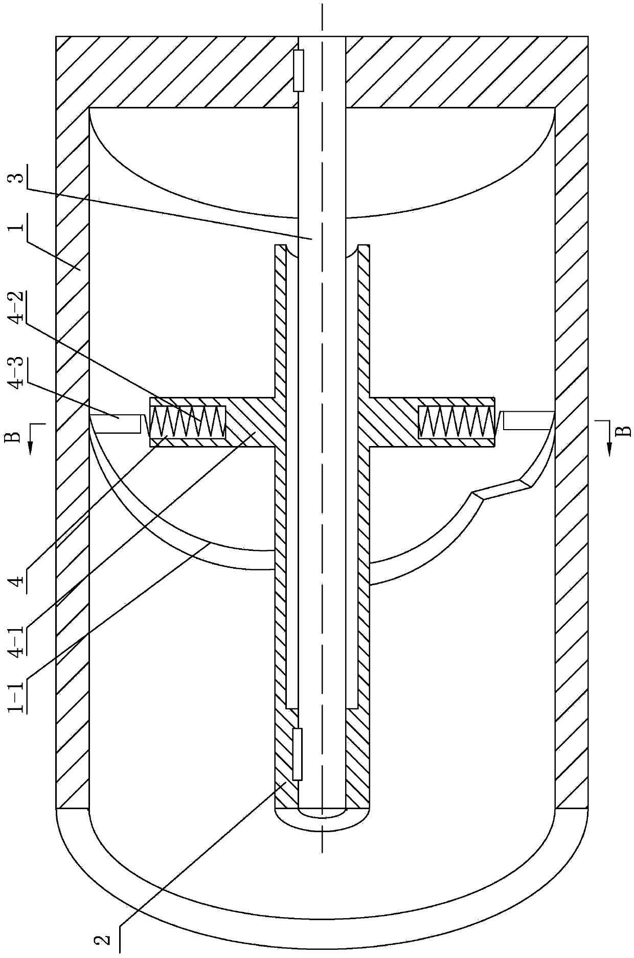
[0009] Specific implementation mode one: combine Figure 1-Figure 2 Explain that the spring cam torsion bar type constant force mechanism of the present embodiment includes an output reel 1, an input shaft 2, a torsion bar 3 and several groups of spring cam mechanisms 4, and each group of spring cam mechanisms 4 includes N sleeves 4- 1. N springs 4-2 and N rollers 4-3, wherein N is a positive integer;

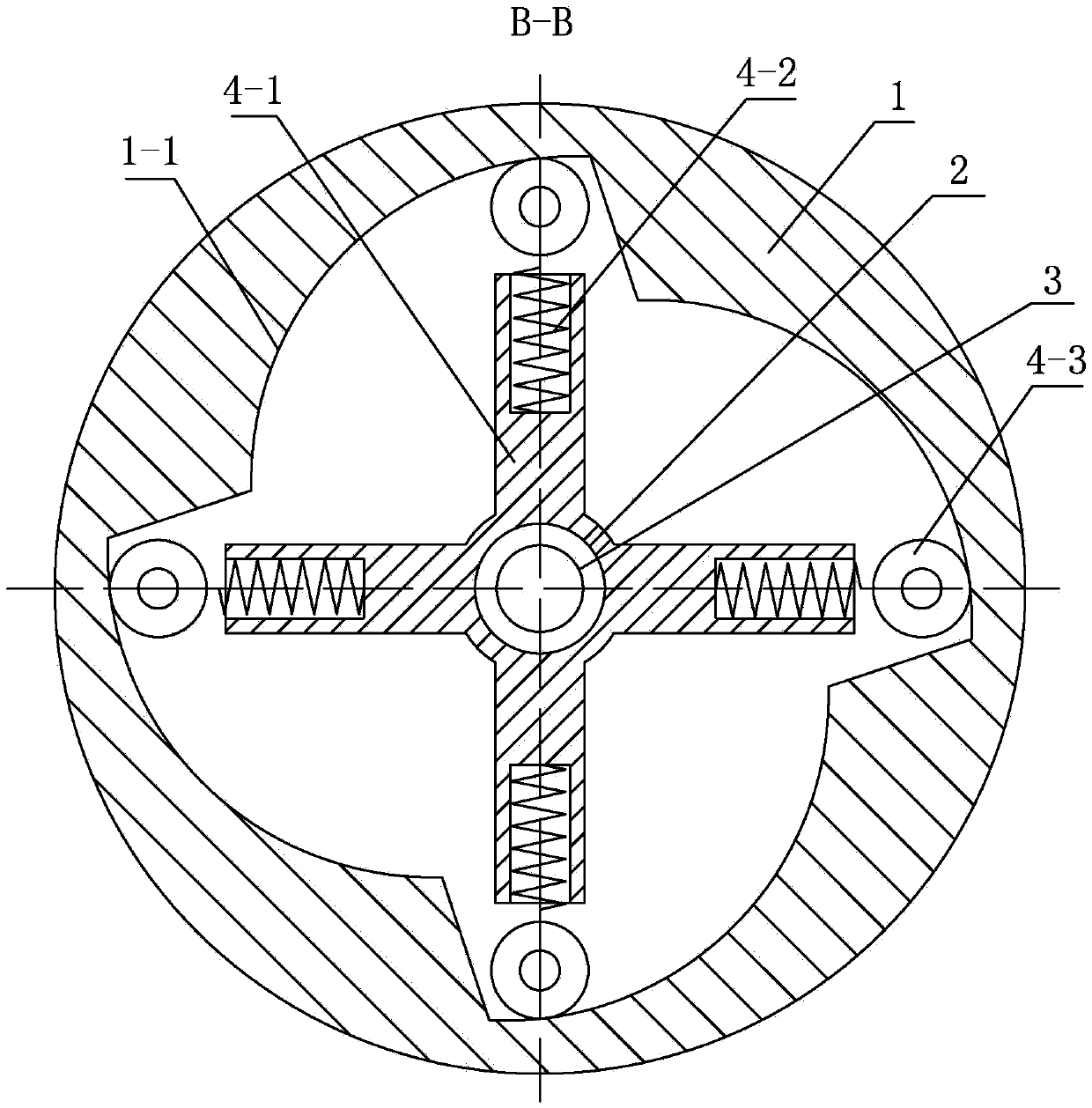
[0010] Several groups of spring cam mechanisms 4 are arranged side by side in the output reel 1 along the axial direction of the output reel, and a torsion bar 3 is arranged in the hollow cavity of the input shaft 2, and the two ends of the torsion bar 3 are connected with the input shaft 2 and the output reel respectively. 1 is fixed, the sleeve 4-1 is a sleeve with grooves, and a plurality of sleeves 4-1 are evenly distributed along the circumference of the input shaft 2 on the outer wall of the input shaft 2, and there are arranged in the sleeve 4-1 The spring 4-2, the two ...

specific Embodiment approach 2

[0017] Specific implementation mode two: combination figure 1 and figure 2 Note that the spring 4-2 in this embodiment is a cylindrical helical compression spring. The structure is simple and easy to use. Others are the same as in the first embodiment.

specific Embodiment approach 3

[0018] Specific implementation mode three: combination figure 2 Note that both the input shaft 2 and the torsion bar 3 in this embodiment are cylindrical structures. Others are the same as in the first or second embodiment.


PUM


Abstract

The invention relates to a constant force loading mechanism, in particular to a spring, cam and torsion bar type constant force mechanism. The problems that the output torque of an existing driven constant force output device is gradually varied torque, the torque value varies linearly along with changes of the rotating angle and is too low, and the existing driven constant force output device cannot output large torque or hardly adapt to demands of various tasks are solved. The spring, cam and torsion bar type constant force mechanism comprises an output winding drum, an input shaft, a torsion bar and a plurality of spring and cam mechanisms, wherein the multiple spring and cam mechanisms are arranged in the output winding drum side by side in the axial direction of the output winding drum; the torsion bar is arranged in a hollow cavity of the input shaft; the two ends of the torsion bar are fixedly connected with the input shaft and the output winding drum; multiple sleeves provided with grooves are evenly distributed in the outer side wall of the input shaft in the circumferential direction of the input shaft; a spring is mounted in each sleeve; the two ends of each spring are connected with the corresponding sleeve and a roller respectively; the rollers abut against a cam guide groove face in the inner side face of the output winding drum correspondingly.

Description

technical field [0001] The invention relates to a constant force loading mechanism, in particular to a passive adaptive constant force loading mechanism. Background technique [0002] Constant force loading mechanism is widely used in paper roll, thermal power generation, material testing, aerospace equipment and other fields, and it can directly affect the safety and reliability of equipment. Especially in the field of aerospace, it is often used as a ground verification method to verify the performance of spacecraft through the constant force mechanism to provide micro-low gravity compensation. Traditional gravity compensation methods include breeding balance, air flotation, water flotation, suspension method, etc. Among them, the gravity simulation of suspension method has two methods: active compensation and passive compensation. The invention creates and designs a passive constant force mechanism to provide constant force output for high-frequency changing loads. [0...

Claims


Application Information

Patent Timeline
Patent Type & Authority Applications(China)
IPC IPC(8): B66D1/30
CPCB66D1/30
Inventor 李楠刘振牛福亮高海波丁亮邓宗全
Owner HARBIN INST OF TECH
Why Eureka
Try Eureka