
Novel pile foundation detection method

A detection method and pile foundation technology, which is applied in the field of construction and foundation foundation, can solve the problems of pile head damage, inability to use pullout detection, and difficult processing of hoops and pressure equipment, so as to ensure the integrity of the pile body and improve the accuracy , the effect of improving the success rate

Inactive Publication Date: 2016-03-02
TIANJIN KEJIAN FOUND ENG TESTING
View PDF0 Cites 15 Cited by
  • Summary
  • Abstract
  • Description
  • Claims
  • Application Information

AI Technical Summary

Problems solved by technology

The deep well in-situ detection method can only detect the bearing capacity of the foundation, and then perform theoretical calculations based on the pile diameter, pile concrete strength, and pile body quality. It cannot directly detect the vertical compressive bearing capacity of the pile, nor can it be used for the uplift resistance of the pile. detection
However, the hoop method can only be used for the pullout detection of pipe piles, and a positive pressure is applied on the outside of the pipe pile, which makes it difficult to process the hoop and pressurizing equipment that generate friction between the hoop and the pipe pile wall, and is prone to local pressure. Too large to damage the pile head

Method used


Image

  • Novel pile foundation detection method
  • Novel pile foundation detection method

Examples


Embodiment Construction

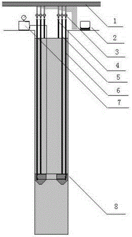
[0024] The present invention will be further described in detail below in conjunction with the accompanying drawings and specific embodiments.

[0025] A) Loading preparation: 50% of the pre-estimated limit value is taken as the test loading limit value, which is divided into 10 levels of loading, and each level is one-tenth of the loading limit value.

[0026] B) Loading detection: carry out loading in stages, and load in equal amounts step by step, in which the first stage is twice as high as the staged load. When the settlement rate of the pile top reaches the relatively stable standard, the next level of load is applied. The relatively stable standard is: the displacement of the pile top within one hour does not exceed 0.1mm, and it occurs twice in a row (starting from the 30th minute after the application of each level of load, calculated from the settlement observation value of three or more times every 30 minutes). When under a certain level of load, the settlement of ...


PUM


Abstract

The invention discloses a novel pile foundation detection method. The method includes the steps that A, in a preparation stage, according to the specific condition of a detected pile foundation and the specific requirements of an experimental objective, the loading position, the loading scheme and the like are determined; B, in a loading detection stage, load boxes are loaded to the pile foundation segment by segment and level by level, the load of the next level can be loaded only after the load of the prior level is relatively stable till the load value reaches a preset maximum detection load value, the pouring quality is detected through the BOTDR distributed optical fiber detection technology, detection data are processed through wavelet analysis, the recorded data are subjected to ANSYS simulated analysis, and defect location and defect degree judgment in space are performed; and C, in an unloading stage, after the pile foundation is loaded to the maximum value, the pressure is maintained for a period of time, the pile foundation starts to be unloaded level by level till the load is zero. By the adoption of the method, the BOTDR distributed optical fiber detection technology is adopted, detection dead zones are reduced, a BOTDR detected data frequency spectrum is processed through wavelet analysis, detection accuracy is improved, a defect analysis model is established, a defect is located and the defect degree is judged.

Description

technical field [0001] The invention mainly relates to the fields of buildings and foundations, in particular to a pile foundation loading detection method. Background technique [0002] With the continuous development of the construction industry, more and more projects use pile foundations. With the widespread use of pile foundations, major engineering quality accidents caused by foundations, pile quality and other reasons occur from time to time. In order to ensure the safety of engineering structures and the safety of life and property of the country and the people, the inspection of pile foundations is becoming more and more important. [0003] The vertical compression and pullout static load testing methods of pile foundations include: surcharge method, ordinary anchor pile method, deep well in-situ test method, self-anchoring method, self-balancing method and hoop method. Various detection methods have their own advantages, but also have their own shortcomings. [0...

Claims


Application Information

Patent Timeline
IPC IPC(8): E02D33/00
Inventor 王官福于松林曹淑洪王莉伟
Owner TIANJIN KEJIAN FOUND ENG TESTING
Learn More