Flow divider priority valve

A priority valve and priority control valve technology, which is applied in fluid pressure actuators, servo motor components, mechanical equipment, etc., can solve the problems of high cost and non-energy saving, and achieve the effects of energy saving, noise reduction and cost reduction

Active Publication Date: 2016-03-02
GUANGXI LIUGONG MASCH CO LTD
View PDF5 Cites 2 Cited by
  • Summary
  • Abstract
  • Description
  • Claims
  • Application Information

AI Technical Summary

Problems solved by technology

[0005] The technical problem to be solved by the present invention is to provide a priority flow diverter valve with a priority flow diversion function to meet the priority of the brake pump in order to solve the problem of high cost and no energy saving when the brake pump and the heat dissipation pump are equipped in the existing loader at the same time. The oil supply of the system, and at the same time meet the oil supply of the hydraulic motor in the heat dissipation system

Method used


Image

  • Flow divider priority valve
  • Flow divider priority valve

Examples


Embodiment 1

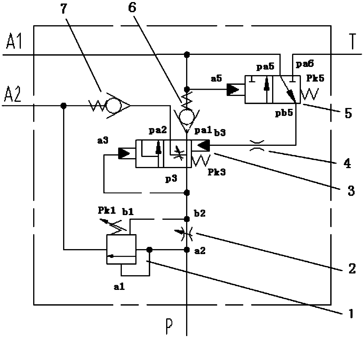
[0028] like figure 1 As shown, the diversion priority valve in this embodiment has an oil inlet P port, an oil return T port, an output A1 port, and an output A2 port for connecting with an external oil circuit, and the oil inlet P port is used for connecting with a pressure oil source connections, such as hydraulic pumps. The oil return T port is used to connect with the oil tank circuit. The output A1 port and the output A2 port are respectively used to connect with two hydraulic actuators, and the oil supply priority of the hydraulic actuator connected to the output A1 port is higher than that of the hydraulic actuator connected to the output A2 port, for example In the loader system, the output A1 port can be used to connect with the hydraulic brake system, and the output A2 port can be used to connect with the hydraulic motor cooling system. The priority diverter valve guarantees the oil supply of the hydraulic brake system first, and the excess flow is supplied to the ...

Embodiment 2

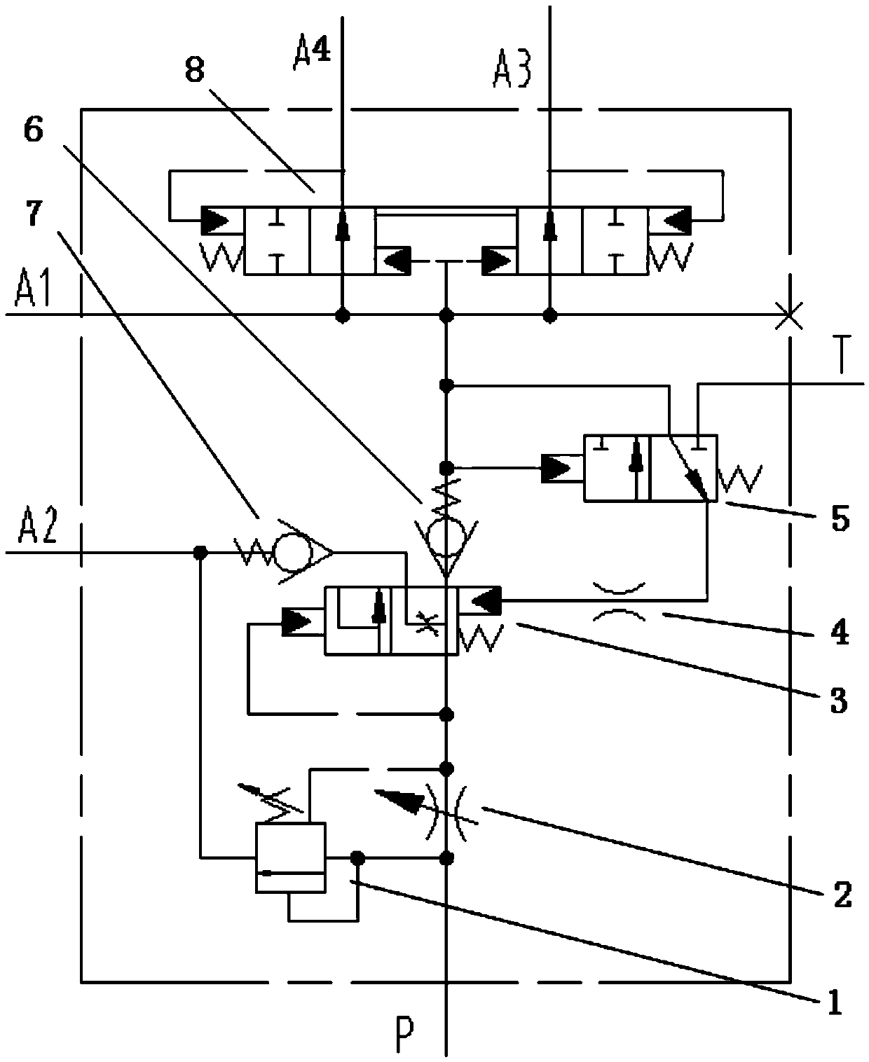
[0036] Compared with the technical solution in Embodiment 1, this embodiment differs in that a pressure reducing valve 8 is connected between the output A1 port and the priority oil outlet pa1 port of the priority valve, through which the pressure reducing valve 8 can output A3 Port and output A4 are connected with the foot brake valve and the accumulator, and the accumulator is charged to store hydraulic energy for the service brake system; the output A1 port is connected with the parking brake valve and supplied to the cylinder of the parking brake system. Oil. The working principle of the priority diverter valve in this embodiment is the same as that of the priority diverter valve in Embodiment 1, and can be used in the hydraulic braking system and hydraulic cooling system of the loader, wherein the output port A2 is connected to the hydraulic motor control valve, The cooling fan hydraulic motor supplies oil, and the output A3 port and output A4 port are connected with the ...


PUM


Abstract

The invention relates to hydraulic elements and provides a flow divider priority valve. The flow divider priority valve aims to solve the problems that a brake pump and a cooling pump are arranged in an existing loading machine, and consequentially the cost is high, and energy saving cannot be achieved. The flow divider priority valve comprises a sequence valve, a throttling valve and a priority valve body, and a priority control valve. The throttling valve is connected with an oil inlet P after being connected with the sequence valve in parallel. An oil outlet of the sequence valve is connected with an output port A2, and the two control ends of the sequence valve are connected with the two ends of the throttling valve. A priority oil outlet of the priority valve is connected with an output port A1, a second oil outlet pa2 of the priority valve is connected with the output port A2, the control end a3 of the priority valve is connected with an oil inlet p3, and the spring cavity control end b3 of the priority valve is connected with an oil port pb5 of the priority control valve. The oil port pb5 and the liquid control end a5 of the priority control valve are connected with the output port A1, and an oil port pb6 of the priority control valve is connected with an oil return port T. The flow divider valve can be applied to a cooling and hydraulic braking system of the loading machine, and oil can be supplied through one hydraulic pump, so that the manufacturing cost is reduced, energy consumption is reduced, and noise is lowered.

Description

technical field [0001] The present invention relates to a hydraulic control element, more specifically, to a diversion priority valve. Background technique [0002] With the mature development of loaders and the improvement of emission noise standards, the technology currently adopted by the loader industry is to configure a heat dissipation pump, drive a hydraulic motor fan through a hydraulic pump to dissipate heat, and use a hydraulic motor fan system to dissipate heat, reducing the noise of the fan. The hydraulic motor fan system is used for heat dissipation. The existing whole machine is equipped with an independent heat dissipation pump to supply oil to the hydraulic motor driving the fan. [0003] In addition, for safety considerations, some high-configuration loaders and stage III and IV stage loaders adopt full hydraulic braking, equipped with a brake pump, and charge the brake accumulator with fluid and store energy through the fluid charging valve. [0004] For t...

Claims


Application Information

Patent Timeline
Patent Type & Authority Applications(China)
IPC IPC(8): F15B13/02
Inventor 边心文吴玉姣
Owner GUANGXI LIUGONG MASCH CO LTD
Why Eureka
Try Eureka