
Automobile and mixed connection type double-middle-shaft transmission thereof

A technology of double countershafts and countershafts, applied to transmission parts, components with teeth, belts/chains/gears, etc., can solve problems such as low power transmission efficiency, reduced transmission efficiency of transmissions, and complex structures, and achieve reduction Energy loss, easy classification and shifting, and the effect of reducing the number

Inactive Publication Date: 2016-03-02
力帆科技(集团)股份有限公司
View PDF7 Cites 0 Cited by
  • Summary
  • Abstract
  • Description
  • Claims
  • Application Information

AI Technical Summary

Problems solved by technology

Through the description of the above working process, for a transmission with one intermediate shaft or two intermediate shafts, in the power transmission process, the power needs to be transmitted from the input shaft to the intermediate shaft through gear meshing, and then to the output shaft through gear meshing. Therefore , when the power is transmitted, the power needs to go through at least two pairs of gear pairs from the input shaft to the output shaft, and the gear mesh must have energy loss, which reduces the transmission efficiency of the transmission
In addition, when increasing the number of gears for a rear-drive transmission, the number of gear pairs on the intermediate shaft and the output shaft is required, which makes the entire transmission complex in structure and heavy in weight
[0005] To sum up, it can be seen that the transmission in the prior art has difficulty in increasing the number of gears, and after increasing the number of gears, the structure is complex, the weight is heavy, and there are also problems of low power transmission efficiency

Method used


Image

  • Automobile and mixed connection type double-middle-shaft transmission thereof
  • Automobile and mixed connection type double-middle-shaft transmission thereof
  • Automobile and mixed connection type double-middle-shaft transmission thereof

Examples


Embodiment Construction

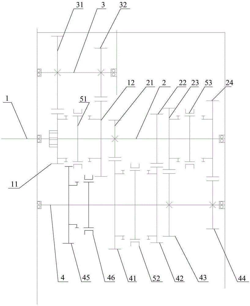
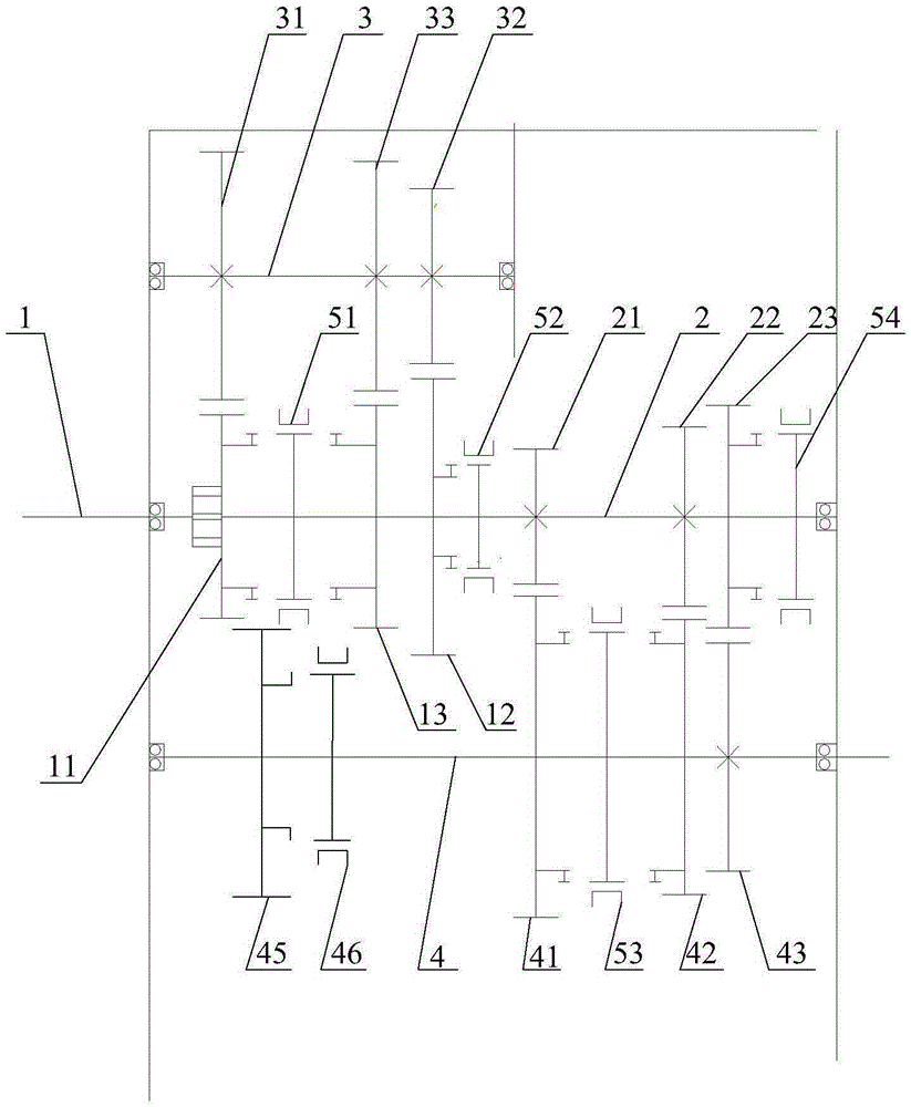
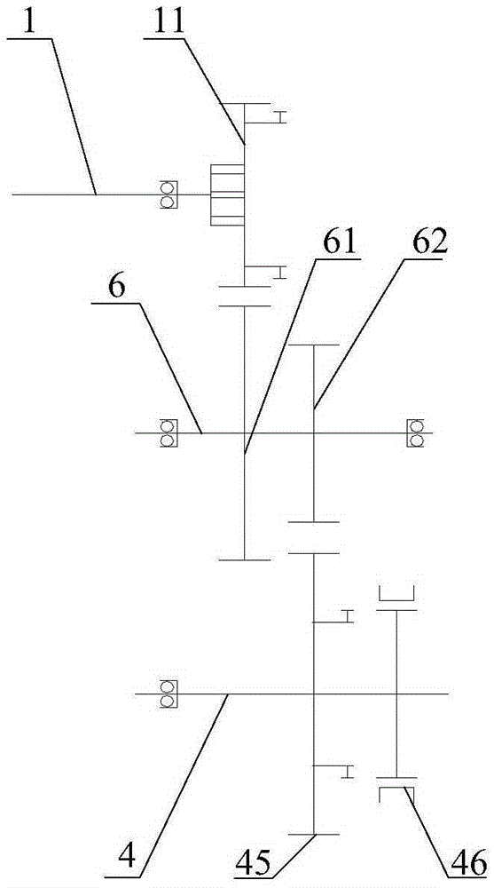
[0041] The core of the present invention is to provide a mixed-connection double countershaft transmission, which can reduce the length of the transmission compared with the existing transmission with the same number of gears. Another core of the present invention is to provide an automobile with the above-mentioned mixed-connection double countershaft transmission.

[0042] The following will clearly and completely describe the technical solutions in the embodiments of the present invention with reference to the accompanying drawings in the embodiments of the present invention. Obviously, the described embodiments are only some, not all, embodiments of the present invention. Based on the embodiments of the present invention, all other embodiments obtained by persons of ordinary skill in the art without making creative efforts belong to the protection scope of the present invention.

[0043] like Figure 1-Figure 3 As shown, the present invention discloses a mixed double coun...


PUM


Abstract

The invention discloses an automobile and a mixed connection type double-middle-shaft transmission thereof. The mixed connection type double-middle shaft transmission comprises an input shaft, a first middle shaft, a second middle shaft, an output shaft, a reverse-gear gear shaft, gears distributed on the shafts, a gear shifting mechanism, a shell, a bearing oil seal and other parts. The number of gears is equal to the product of the number of gears on the first middle shaft and the number of gears on the second middle shaft. The number of gears of an existing transmission is equal to the sum of the number of all gear meshing pairs of the existing transmission. Due to the adoption of the transmission, on the premise that the size and the weight of a traditional six-gear transmission are unchanged, the traditional six-gear transmission can be changed into an eight-gear or nine-gear transmission, the dynamic performance, fuel economical efficiency and driving comfort of the whole automobile are obviously improved, and the transmission is suitable for serving as an AMT automatic transmission. A reverse-gear gear is arranged to be a bevel gear, gear shifting is smoother than a spur gear, and meshing noise is obviously lowered.

Description

technical field [0001] The invention relates to the technical field of transmissions, and more specifically relates to a mixed-connection double countershaft transmission. Background technique [0002] Since the transmission was born, it has become an indispensable part of the car, and there are more and more types, and the development of the transmission tends to be diversified. Mainly divided into: manual transmission (MT), hydraulic automatic transmission (AT), electromechanical automatic transmission (AMT), continuously variable transmission (DCT). [0003] At present, the vast majority of passenger cars are front-wheel drive, and the matching transmission is a two-shaft transmission, including an input shaft and an output shaft, and the two shafts are arranged in parallel. The input shaft is also the driven shaft of the clutch, and the output shaft is also The drive shaft of the main reducer. Take the five-speed transmission as an example: in order to realize the gear...

Claims


Application Information

Patent Timeline
Patent Type & Authority Applications(China)
IPC IPC(8): F16H57/023F16H57/038F16H57/02
CPCF16H57/02F16H57/023F16H57/038F16H2057/02043F16H2057/02091F16H2057/02086
Inventor 李学龙
Owner 力帆科技(集团)股份有限公司
Learn More