Membrane servo valve driven by piezoelectric ceramics

A piezoelectric ceramic drive and piezoelectric ceramic technology, which is applied in the field of servo valves to achieve the effects of reducing pressure difference, low manufacturing cost and improving control accuracy

Inactive Publication Date: 2016-03-02
SHANDONG UNIV
View PDF8 Cites 13 Cited by
  • Summary
  • Abstract
  • Description
  • Claims
  • Application Information

AI Technical Summary

Problems solved by technology

[0007] After searching, there is no design case of membrane servo valve with pressure balance oil cavity directly driven by piezoelectric ceramics

Method used


Image

  • Membrane servo valve driven by piezoelectric ceramics

Examples


Embodiment 1

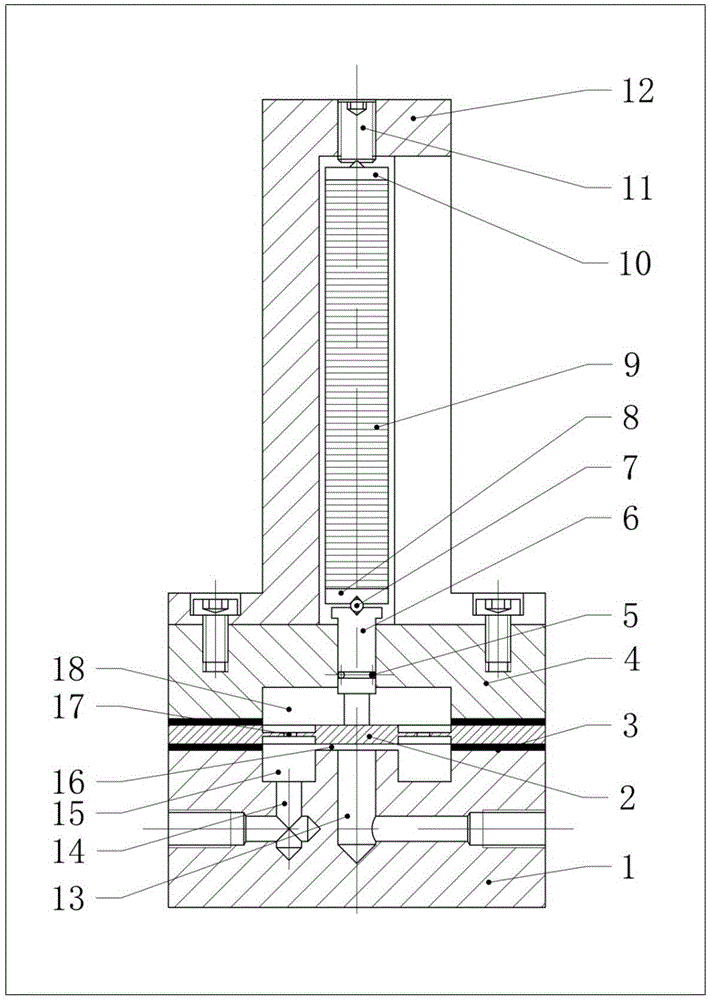
[0034] A piezoceramic driven thin-film servo valve, such as figure 1 As shown, it includes a housing composed of a lower valve body 1, an upper valve body 4 and a piezoelectric ceramic base 12. The central hole 13 of the lower valve body 1 is the hydraulic oil inlet, and the annular throttling oil of the lower valve body 1 Chamber 15 is connected to hydraulic oil outlet 14 . There is a circular pressure balance oil chamber 18 inside the upper valve body 4 . Between the upper valve body 4 and the lower valve body 1 is an elastic metal film 2 and adjusting gaskets 3 on both sides. The film 2 is designed as an island-shaped flexible hinge structure with a thick middle throttling part and a thin elastically deformed annular area around it. Four communication holes 17 connecting the throttling oil chamber 15 and the pressure balance oil chamber 18 are evenly distributed in the flexible hinge area. The central island of the membrane 2 and the annular boss at the center of the lowe...


PUM


Abstract

The invention discloses a membrane servo valve driven by piezoelectric ceramics. The membrane servo valve comprises an upper valve body and a lower valve body, wherein a membrane is arranged between the upper valve body and the lower valve body; a cylindrical balancing oil cavity is formed between the upper valve body and the membrane; a ring-shaped throttling oil cavity is formed between the membrane and the lower valve body; the balancing oil cavity and the throttling oil cavity are communicated with each other; an ejector rod vertically penetrates through a space between the upper valve body and the balancing oil cavity; one end of the ejector rod is arranged with a set spacing distance to the membrane, or in contact with the membrane; one of the piezoelectric ceramics used for pushing the ejector rod to move is arranged at the other end of the ejector rod. The membrane servo valve has the benefits that through precise control of a throttling interval, the pressure and the flow can be precisely and actively controlled; the center of the membrane is set to be a central island shape, the central island shape is rigid, and a deformation zone around the central island shape is flexible, so as to improve the dynamic frequency of the membrane; meanwhile, the throttling interval control precision is improved, and the whole membrane servo valve is simple in structure, reliable in function and low in manufacturing cost.

Description

technical field [0001] The invention relates to a servo valve, in particular to a piezoelectric ceramic driven thin-film servo valve. Background technique [0002] At present, the application fields of hydraulic servo control systems are becoming wider and wider, which puts forward extremely high requirements for the performance of electro-hydraulic servo valves: high frequency response, high precision, simplicity and reliability, etc. The traditional electromagnetic servo valve can no longer meet the high-response control requirements, so the development of a new type of high-response active control servo valve has become a difficult problem in the field of hydraulic servo control. [0003] In the research and development process of many new micro-displacement and high-response drivers, piezoelectric ceramic materials have become the preferred driving components in precision positioning systems because of their advantages such as small size, high energy density, high resolu...

Claims


Application Information

Patent Timeline
Patent Type & Authority Applications(China)
IPC IPC(8): F16K31/02F16K7/14F15B13/02
CPCF15B13/02F16K7/14F16K31/004
Inventor 李华超路长厚潘伟刘自超
Owner SHANDONG UNIV
Why Eureka
Try Eureka