Working roll bending device of plate band rolling mill

A technology of work roll bending and work roll, which is applied in the direction of metal rolling stand, metal rolling mill stand, metal rolling, etc., which can solve the problem of increased oil supply time of the hydraulic system, reduced service life, and unfavorable normal use of stand rolls and other problems, to achieve the effect of reducing compensation amount and compensation time, reducing maintenance frequency and time, and reducing oil supply working time

Active Publication Date: 2011-01-26
MCC CAPITAL ENGINEERING & RESEARCH +1
View PDF9 Cites 10 Cited by
  • Summary
  • Abstract
  • Description
  • Claims
  • Application Information

AI Technical Summary

Problems solved by technology

However, for large rolling mills with large opening changes, such as large medium and heavy plate rolling mills, large wide and heavy plate rolling mills, etc., the above technical solutions are not suitable, and there are certain limitations in the structure of this type of bending device. As a result, the stroke of the upper bending cylinder is relatively long, the guiding and stability of the bending cylinder are poor, the seal is easily damaged, and the service life is short, so the guidance and protection of the upper cylinder must be added; and further, because the upper bending cylinder must always be Close to the upper work roll, follow the movement of the upper roll system, and the opening degree of the rolling mill changes frequently, which will inevitably lead to frequent movements of the upper bending cylinder, which increases the frequency of servo hydraulic valve movements and reduces its service life. The stroke is relatively long, the amount of hydraulic oil required is relatively large, and the oil supply time of the hydraulic system is bound to increase.
[0005] And as the technical solution disclosed in Chinese patent No. ZL200710203401.7, the upper bending roller device is roughly arranged in the boss of the bearing seat of the upper backup roller, and the lower bending roller cylinder adopts a separate cylinder block, which is installed at the waist of the archway. This structure can shorten the stroke of the bending cylinder on the large-opening rolling mill, thereby enhancing the guiding and stability, improving the reliability of the seal, and reducing the amount of hydraulic oil required, but the above-mentioned structure , the bending cylinder is installed by drilling holes on the boss under the bearing seat of the upper back-up roller, so the connecting bolts that carry the end cover of the piston chamber and the bearing seat have poor load-carrying reliability; the pressure used for the control of the bending cylinder Higher, and the bearing seat is cast steel, the inner quality of the casting is relatively poor, which is easy to cause leakage; at the same time, the lower part of the bearing seat of the upper back-up roller needs to be designed more, the structure is relatively complicated, and the weight of the equipment is also heavy
[0006] In addition, in the work of large rolling mills, the stand rolls also play a very important role, such as the transportation of slabs, auxiliary steel bite, etc., especially for the rolling of short slabs in large medium and heavy plate mills, the transmission of stand rolls It is advisable to use separate transmission, and the use of centralized transmission has the problems of unreliable sealing and lubricating oil leakage
However, the structure of the existing roll bending device, such as the structure disclosed in the above-mentioned prior patent, all has the problem that the rolls of the rolling mill stand are not easy to carry out separate transmission arrangements. Generally, the stand rolls far away from the rolls are individually driven. The two rack rolls close to the roll adopt centralized transmission, or adopt all centralized transmission, and set up a transmission gear distribution box, which in turn brings about the problem of rack roll transmission sealing and lubrication, which has a very adverse effect on the normal use of the rack roll

Method used


Image

  • Working roll bending device of plate band rolling mill
  • Working roll bending device of plate band rolling mill
  • Working roll bending device of plate band rolling mill

Examples


Embodiment Construction

[0066] In order to have a clearer understanding of the technical features, purposes and effects of the present invention, the specific implementation manners of the present invention will now be described with reference to the accompanying drawings.

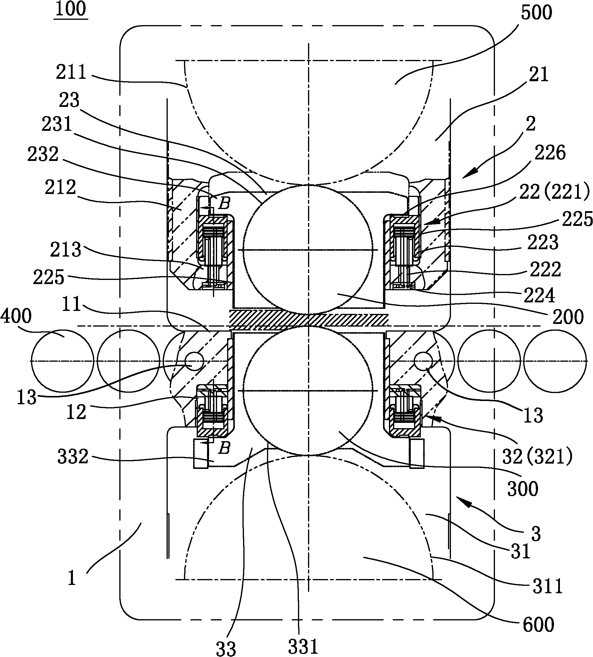
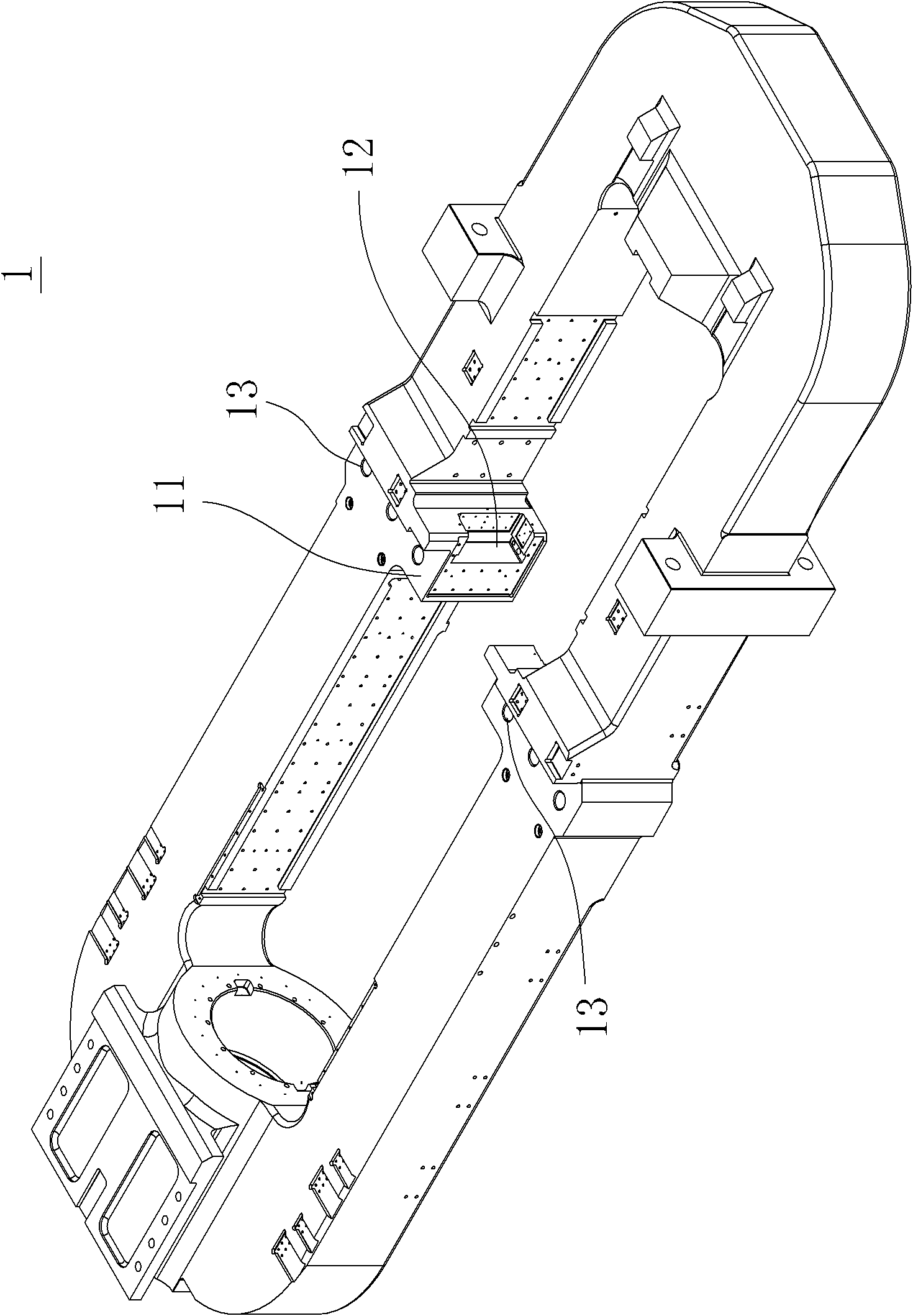
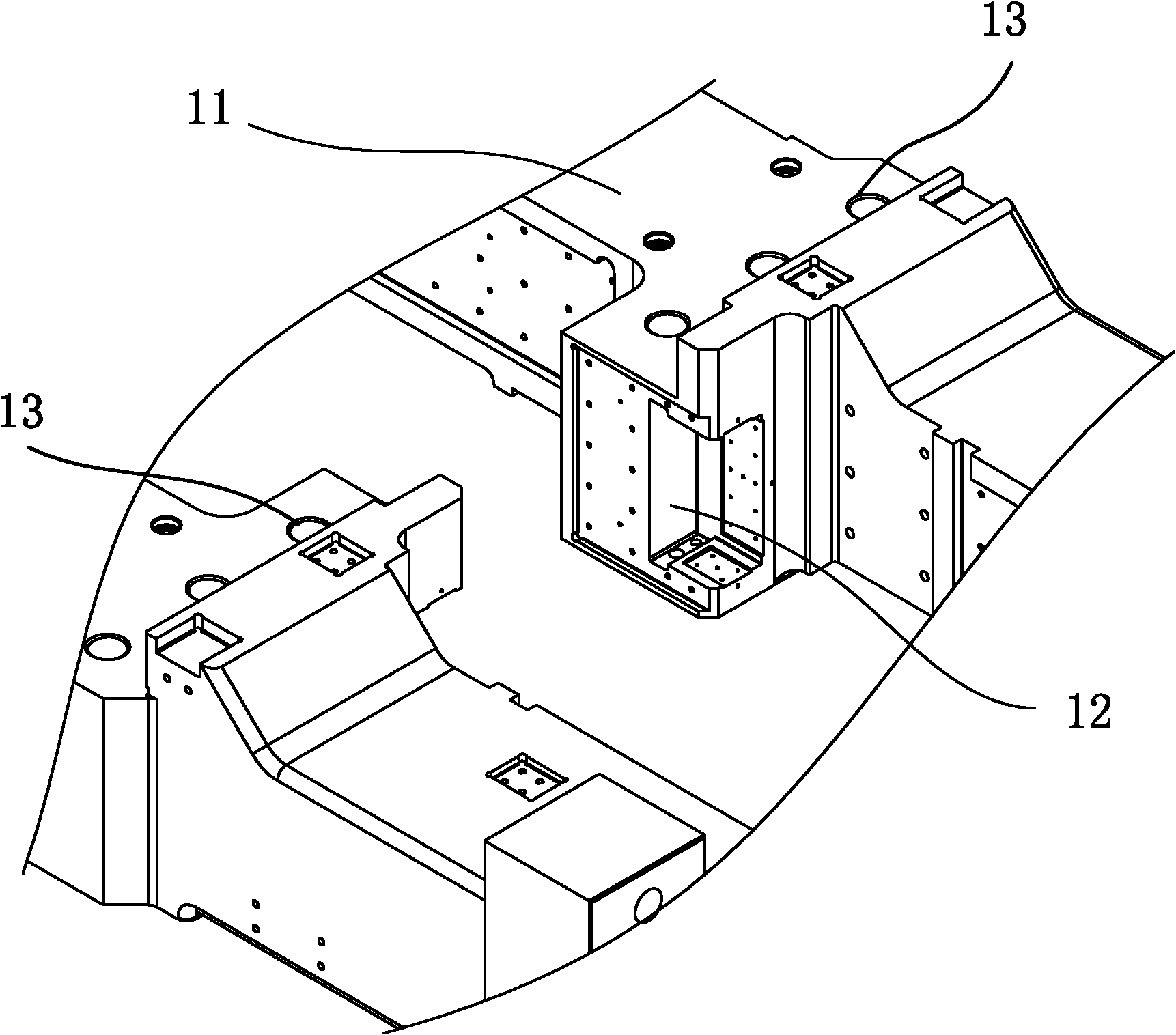
[0067] Please refer to figure 1 and figure 2 ,in figure 1 It is a schematic diagram of the overall structure of the work roll bending device of the strip mill of the present invention, figure 2 It is a schematic diagram of the archway of the work roll bending device of the strip mill of the present invention. As shown in the figure, the roll bending device 100 of the present invention is arranged at both ends of the upper work roll 200 and the lower work roll 300, that is to say, on the upper work roll 200 and the two ends of the lower work roll 300 are respectively equipped with the roll bending device 100 of the present invention, so as to realize the support, balance and roll bending control of the work roll device during ...


PUM


Abstract

The invention discloses a working roll bending device of a plate band rolling mill. The device is fixedly arranged on a rolling mill stand, and roll bending devices are arranged on two end parts of an upper working roll and a lower working roll so as to carry out supporting, balancing and roll bending control on the upper working roll and the lower working roll to improve the convexity of a loaded roll gap between the upper working roll and the lower working roll and control the plate shape. The roll bending device comprises a memorial archway, upper roll bending devices and lower roll bending devices, wherein the memorial archway is a framework body, and upright posts at the left side and the right side of the memorial archway are respectively inwards and convexly provided with a waist bump; the upper roll bending devices can be slidably arranged in the memorial archway, positioned above the waist bump and assembled at two ends of the upper working roll; and the lower roll bending devices can be slidably arranged in the memorial archway, positioned below the upper roll bending device and assembled at two ends of the lower working roll. The working roll bending device of the plate band rolling mill can meet the working requirement of a large large-openness plate band rolling mill and has the advantages of reliable rolling quality and long service life.

Description

technical field [0001] The invention relates to a roll bending device, in particular to a work roll bending device of a strip mill. Background technique [0002] A variety of means and methods are used in modern strip mills to improve the roll gap crown and control the shape. The hydraulic roll bending control method is convenient for online real-time control, can quickly change the shape of the roll gap, and has a strong ability to control the shape of the plate. advantages and has been widely used. [0003] At present, positive roll bending control of work rolls is often used in large-scale strip mills. A hydraulic roll bending device is installed between the upper and lower work roll chocks to apply a bending force in the same direction as the rolling force to the upper and lower work roll chocks to change The crown of the loaded roll gap between the upper and lower work rolls of the rolling mill, thereby controlling the shape of the strip. Most of the equipment structu...

Claims


Application Information

Patent Timeline
Patent Type & Authority Applications(China)
IPC IPC(8): B21B31/26B21B31/32
Inventor 任际军赵容仲张春光王颖江涛徐永华张俊伟刘延军李碧玲周雅婷张薇
Owner MCC CAPITAL ENGINEERING & RESEARCH
Why Eureka
Try Eureka