Electromagnetic drive adhesive dispensing valve comprising flexible amplification arm

A technology of flexible amplifying arm and driving point, which is applied to devices and coatings that apply liquid to the surface, can solve the problems of difficult to achieve high-viscosity glue injection, large injection needles, complicated manufacturing process, etc. The viscosity of the glue liquid is large, which is conducive to heat dissipation and good heat dissipation performance.

Inactive Publication Date: 2013-02-27
CENT SOUTH UNIV
View PDF4 Cites 10 Cited by
  • Summary
  • Abstract
  • Description
  • Claims
  • Application Information

AI Technical Summary

Problems solved by technology

Due to the limitations of the driving force and the stroke of the injection needle, it is difficult for the current glue injection technology to achieve a high speed of the injection needle, so it is difficult to realize the injection of high-viscosi

Method used


Image

  • Electromagnetic drive adhesive dispensing valve comprising flexible amplification arm
  • Electromagnetic drive adhesive dispensing valve comprising flexible amplification arm
  • Electromagnetic drive adhesive dispensing valve comprising flexible amplification arm

Examples


Embodiment 1

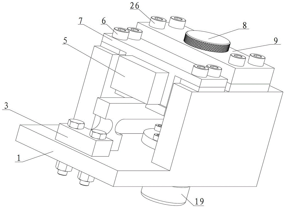
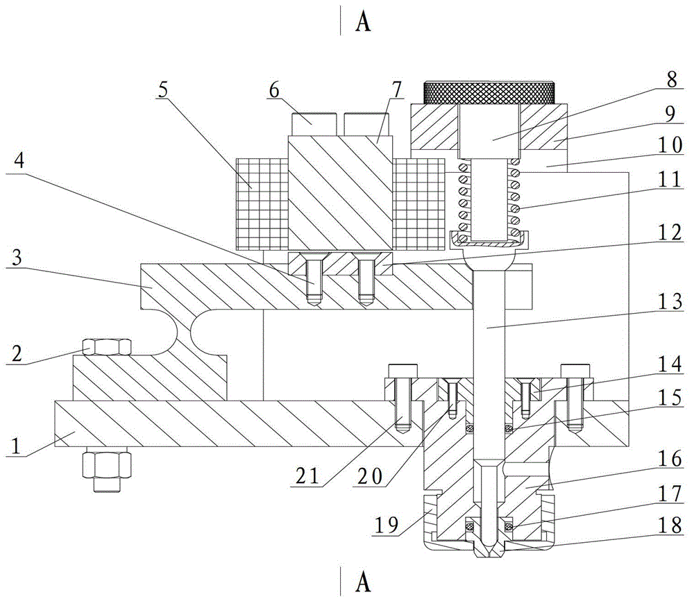
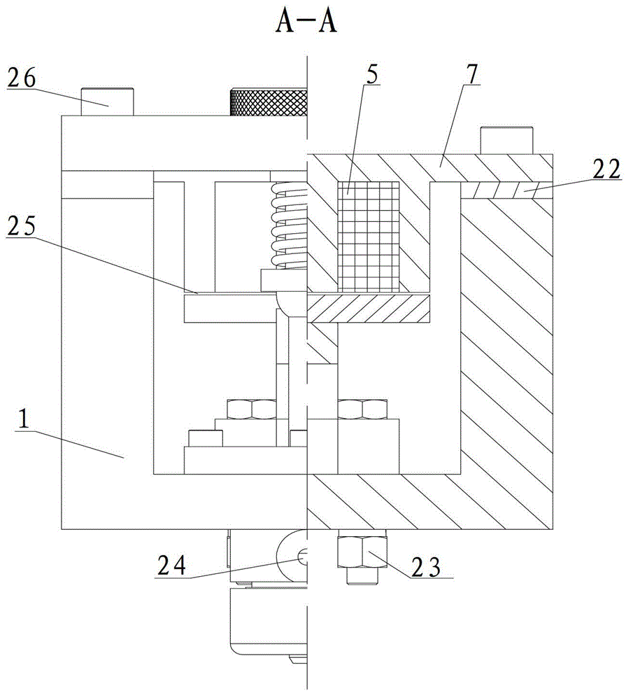
[0024] see figure 1 , figure 2 and image 3 , the bracket 1 is connected with other parts as the support of several other parts; the electromagnet is composed of an E-type electromagnet core 7 and an electromagnetic coil 5, and the electromagnet core 7 and the air gap adjusting gasket 22 are fixed on the bracket by the first screw 6 1, the length of the air gap 25 between the electromagnet core 7 and the armature 12 can be adjusted by changing the thickness of the air gap adjusting gasket 22, and finally adjust the stroke of the injection needle 13; Two screws 4 are rigidly connected; one end of the flexible amplifying arm 3 is fixed on one end of the bracket 1 by a bolt 2 and a nut 23, and the other end of the flexible amplifying arm 3 is connected with the injection needle 13 in transmission, and the connecting part is a smooth spherical surface; the supporting horizontal plate 9 and The gasket 10 is fixed on the bracket 1 by the third screw 26, and a compression spring 1...

Embodiment 2

[0031] refer to Figure 4 and Figure 5, the bracket 1 is connected with other parts as the support of several other parts; the electromagnet is composed of an E-type electromagnet core 7 and an electromagnetic coil 5, and the electromagnet core 7 and the air gap adjusting gasket 22 are fixed on the bracket by the first screw 6 1, the length of the air gap 25 between the electromagnet core 7 and the armature 12 can be adjusted by changing the thickness of the air gap adjusting gasket 22, and finally adjust the stroke of the injection needle 13; Two screws 4 are rigidly connected; one end of the flexible amplifying arm 3 is fixed on one end of the bracket 1 by a bolt 2 and a nut 23, and the other end of the flexible amplifying arm 3 is connected with the injection needle 13 in transmission, and the connecting part is a smooth spherical surface; the supporting horizontal plate 9 and The spacer 10 is fixed on the support 1 by the third screw 26, the adjusting screw 8 is threaded...


PUM


Abstract

The invention discloses an electromagnetic drive adhesive dispensing valve comprising a flexible amplification arm. The electromagnetic drive adhesive dispensing valve comprising the flexible amplification arm comprises an adhesive cavity (16), a nozzle (18) and an ejecting needle (13), the adhesive cavity (16), the nozzle (18) and the ejecting needle (13) are installed at one end of a support (1), one end of the flexible amplification arm (3) is installed at the other end of the support (1), the other end of the flexible amplification arm (3) is in transmission connection with the ejecting needle (13), a supporting horizontal plate (9) is arranged on the support (1), a regulating screw (8) is arranged on the supporting horizontal plate (9), a compression spring (11) is arranged between the ejecting needle (13) and the regulating screw (8), an armature (12) is installed on the flexible amplification arm (3), and an electric magnet acting on the armature (12) is installed on the support (1). The electromagnetic drive adhesive dispensing valve comprising the flexible amplification arm is rapid in response, simple in structure, large in sprayable adhesive viscosity and adjustable in spraying speed and adhesive spraying amount.

Description

technical field [0001] The invention relates to a dispensing device, in particular to an electromagnetically driven dispensing valve with a flexible amplifying arm. Background technique [0002] At present, dispensing equipment used in microelectronics and optoelectronic packaging is very common. According to the usage conditions, dispensing can be divided into contact dispensing and non-contact dispensing. The general non-contact dispensing equipment pushes the injection needle to move up and down in a certain way to realize the injection process of extruding glue. The viscosity of the glue that can be sprayed by the jet dispensing valve is directly related to the speed of the downward movement of the jet needle. Under certain conditions, the faster the downward movement of the injection needle, the greater the viscosity of the glue can be injected. Due to the limitations of the driving force and the stroke of the injection needle, it is difficult for the current glue inj...

Claims


Application Information

Patent Timeline
IPC IPC(8): B05C11/10B05C5/02
Inventor 邓圭玲周灿李辉邓衍澄
Owner CENT SOUTH UNIV
Why Eureka
Try Eureka