Air conditioner indoor unit

An air-conditioning indoor unit and centrifugal fan technology, used in air-conditioning systems, space heating and ventilation, household heating and other directions, can solve the problems of large installation space, unsightly appearance, and low air volume, etc., to reduce airflow pressure loss, improve Comfortable experience, the effect of reducing air loss

Active Publication Date: 2016-03-02
QINGDAO HAIER AIR CONDITIONER GENERAL CORP LTD
View PDF6 Cites 4 Cited by
  • Summary
  • Abstract
  • Description
  • Claims
  • Application Information

AI Technical Summary

Problems solved by technology

One disadvantage of this kind of air supply is that the air sent out is all heat exchange air, the air volume is small, and the indoor air circulation speed is slow; another disadvantage is that the air sent out is not soft enough, especially in the cooling mode, the cool air blown out The wind blows directly on the user, and the user feels uncomfortable
[0003] In addition, because the indoor units of the existing wall-mounted air conditioners are long strips, they are not only bulky and occupy a large installation space, but also not beautiful enough to meet the diverse needs of the market.

Method used


Image

  • Air conditioner indoor unit
  • Air conditioner indoor unit
  • Air conditioner indoor unit

Examples


Embodiment Construction

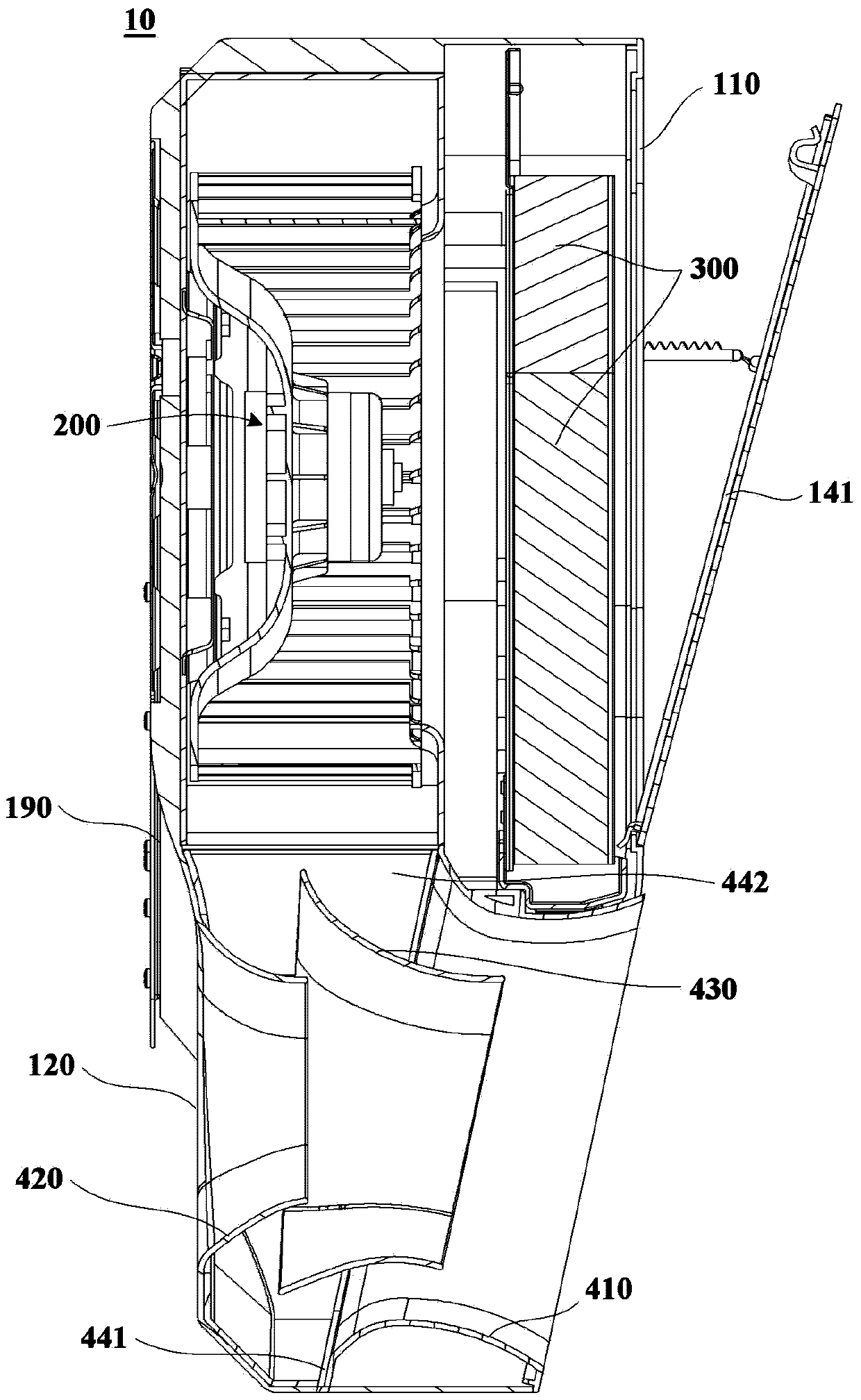
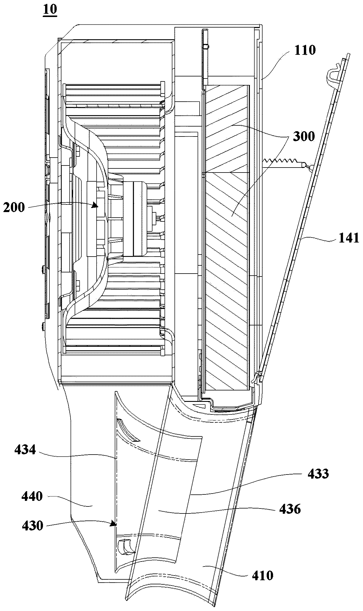
[0060] figure 1 is a schematic structural diagram of an air conditioner indoor unit 10 according to an embodiment of the present invention; figure 2 is a schematic cross-sectional view of an air conditioner indoor unit 10 according to an embodiment of the present invention; image 3 is a partial schematic sectional view of the air conditioner indoor unit 10 according to one embodiment of the present invention. see Figure 1 to Figure 3 , the air conditioner indoor unit 10 according to the embodiment of the present invention includes a casing 100 and a centrifugal fan 200 inside the casing 100 . The casing 100 has a first air inlet 110 for introducing air in the environment space (such as indoor air), a second air inlet 120 and an air outlet 130 for sending mixed air into the environment space. The second air inlet 120 may be formed at the rear of the housing 100 , and the air outlet 130 may be formed at the front of the housing 100 opposite to the second air inlet 120 . T...


PUM


Abstract

The invention provides an air conditioner indoor unit. The air conditioner indoor unit comprises a shell, a centrifugal fan, a heat exchanger and a draining air guiding device, wherein the shell is provided with a first air inlet, a second air inlet and an air outlet; the first air inlet is formed in the upper portion of the shell; the air outlet and the second air inlet are formed in the front side and the rear side of the lower portion of the shell respectively; the centrifugal fan is arranged in a containing space inside the shell and arranged to suck environmental air from the environment around the first air inlet and urge the air to flow to the lower portion of the shell; the heat exchanger is arranged on an air inlet channel between the centrifugal fan and the first air inlet in the shell; the draining air guiding device is arranged on the lower portion of the containing space inside the shell and arranged to mix airflow from the centrifugal fan and airflow from the second air inlet and blow out the mixed airflow through the air outlet. A middle air guiding ring of the draining air guiding device is formed in a mode that the connecting line of the circle center of the projection line of the rounded top contour of the middle air guiding ring and the midpoint of the projection line of the front end edge of the middle air guiding ring forms a first included angle with the projection line of the front end edge of the middle air guiding ring. The air conditioner indoor unit is capable of increasing the air supplying amount of an air conditioner.

Description

technical field [0001] The invention relates to the technical field of air conditioning, in particular to an air conditioner indoor unit. Background technique [0002] The indoor units of the existing wall-mounted air conditioners are all strip-shaped, and use a cross-flow fan and a bent evaporator for air supply. The air after heat exchange of the bent evaporator is directly blown out from the air outlet under the action of the internal cross-flow fan, and all the air blown out is heat exchange air. One disadvantage of this kind of air supply is that the air sent out is all heat exchange air, the air volume is small, and the indoor air circulation speed is slow; another disadvantage is that the air sent out is not soft enough, especially in the cooling mode, the cool air blown out The wind blows directly on the user, and the user feels uncomfortable. [0003] In addition, because the indoor units of the existing wall-mounted air conditioners are elongated, they are not on...

Claims


Application Information

Patent Timeline
Patent Type & Authority Applications(China)
IPC IPC(8): F24F1/00F24F13/10
CPCF24F1/0003F24F13/10
Inventor 戴现伟王永涛闫宝升单翠云关婷婷
Owner QINGDAO HAIER AIR CONDITIONER GENERAL CORP LTD
Why Eureka
Try Eureka