
Span-adjustable bending test clamp with positioning function

A bending test and fixture technology, which is applied in the direction of applying stable bending force to test material strength, strength characteristics, measuring devices, etc., can solve the problems of positioning accuracy, fixed span, and insufficient wear-resistant test pieces, and achieve the goal of reducing design costs Effect

Inactive Publication Date: 2016-03-02
CHINA AIRPLANT STRENGTH RES INST
View PDF6 Cites 22 Cited by
  • Summary
  • Abstract
  • Description
  • Claims
  • Application Information

AI Technical Summary

Problems solved by technology

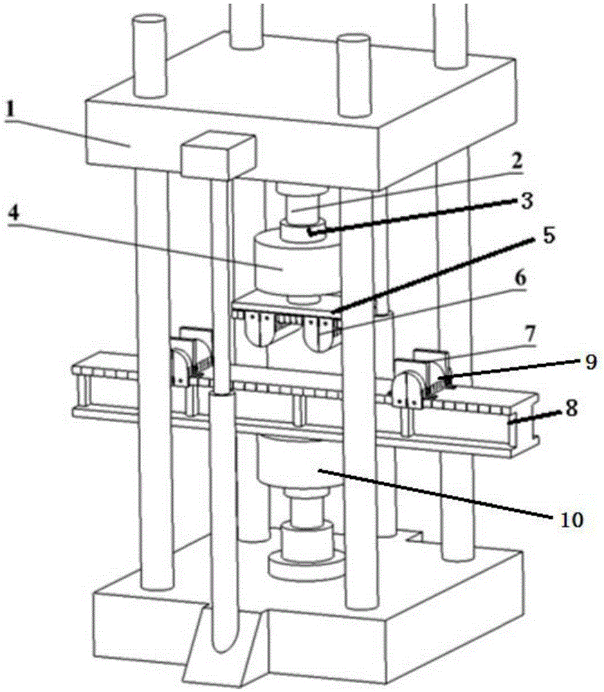
[0004] In order to solve the above problems, the present invention proposes a bending test fixture device that can meet the requirements of three-point and four-point bending tests at the same time, is adjustable in span, easy to replace, has a positioning function, and can be used repeatedly. In the development of the No. 1 bending test fixture, the span is fixed and easy to wear, and the positioning accuracy of the test piece is insufficient, forming the test capability for large deformation, large load and high-precision control of the new bending test piece

Method used


Image

  • Span-adjustable bending test clamp with positioning function
  • Span-adjustable bending test clamp with positioning function
  • Span-adjustable bending test clamp with positioning function

Examples


Embodiment Construction

[0024] In order to make the objectives, technical solutions and advantages of the present invention clearer, the technical solutions in the embodiments of the present invention will be described in more detail below in conjunction with the drawings in the embodiments of the present invention. In the drawings, the same or similar reference numerals denote the same or similar elements or elements having the same or similar functions throughout. The described embodiments are some, but not all, embodiments of the invention. The embodiments described below by referring to the figures are exemplary and are intended to explain the present invention and should not be construed as limiting the present invention. Based on the embodiments of the present invention, all other embodiments obtained by persons of ordinary skill in the art without creative efforts fall within the protection scope of the present invention. Embodiments of the present invention will be described in detail below ...


PUM


Abstract

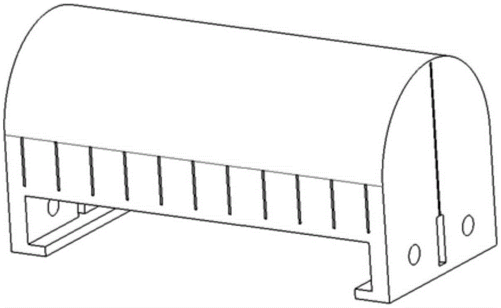
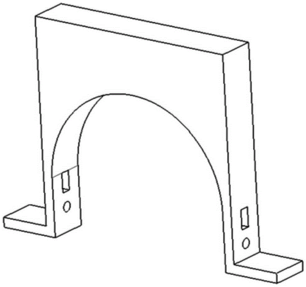
The invention discloses a span-adjustable bending test clamp with a positioning function, and belongs to the technical field of aircraft structure bending tests. The clamp comprises two clamp upper fulcrums, two clamp lower fulcrums, an upper clamp guide rail platform, a lower clamp guide rail platform and an acting barrel. The upper clamp guide rail platform and the lower clamp guide rail platform are provided with sliding rails respectively and provided with scales in the direction of the sliding rails. Threaded holes are formed in the sliding rails. The clamp upper fulcrums and the upper clamp guide rail platform are in sliding connection and are fixed through bolts. The clamp lower fulcrums and the lower clamp guide rail platform are in sliding connection and are fixed through bolts. The lower clamp guide rail platform is fixed to a test machine loading frame through a test machine lower chuck. The upper clamp guide rail platform is fixedly connected with the acting barrel through a test machine upper chuck. The problems that when large-load and large-deformation bend tests are carried out, the span of clamp fulcrums cannot be adjusted, and a clamp cannot adapt to test piece size changes or meet design requirements are solved.

Description

technical field [0001] The invention belongs to the technical field of aircraft structure bending tests, in particular to a bending test fixture with adjustable span and positioning function. Background technique [0002] There are a large number of beam structures in aircraft wing structures to resist bending loads and deformations. The determination of the bending performance data of materials and structures through three-point and four-point bending tests is the basic premise for reliability design, analysis and verification in the fields of aerospace, transportation, machinery and chemical industry. During the process of take-off-cruising-landing, the mid-spar structure of the wing mainly bears the repeated action of bending load, which is prone to fatigue failure. Sometimes under the action of gust load, the wing structure will be greatly deformed, which is not conducive to the safe control and normal flight of the aircraft. In addition, in the current aircraft struct...

Claims


Application Information

Patent Timeline
Patent Type & Authority Applications(China)
IPC IPC(8): G01N3/04G01N3/20
CPCG01N3/04G01N3/20
Inventor 樊俊铃陈先民庞宝才张文东李三元
Owner CHINA AIRPLANT STRENGTH RES INST
Learn More