Scanable tray for producing a dental prosthesis

A technology for trays and dentures, applied in the directions of additive manufacturing, manufacturing tools, applications, etc., which can solve the problems of large oral cavity, uncomfortable removal of patients, and deterioration of dentures.

Active Publication Date: 2016-03-02
古莎有限公司
View PDF14 Cites 16 Cited by
  • Summary
  • Abstract
  • Description
  • Claims
  • Application Information

AI Technical Summary

Problems solved by technology

[0005] The disadvantage associated with this is that the parts of the tray attached to each other are relatively large compared to the patient's mouth, so that the patient often experiences uncomfortable

Method used


Image

  • Scanable tray for producing a dental prosthesis
  • Scanable tray for producing a dental prosthesis
  • Scanable tray for producing a dental prosthesis

Examples


Embodiment Construction

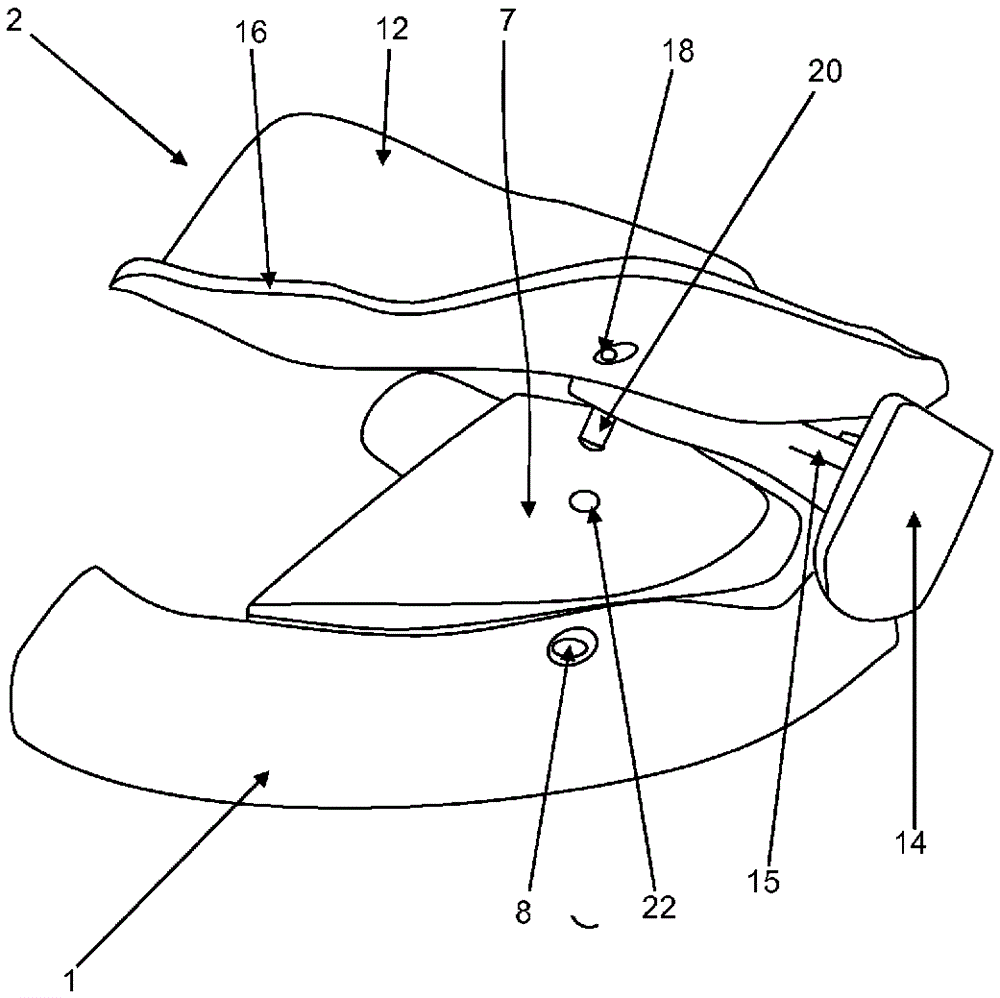
[0052] figure 1 A schematic perspective view of a tray according to the invention for dental impressions is shown. The tray is divided into two tray sections1,2. The first tray part 1 is intended for the lower jaw and the second tray part 2 is intended for the upper jaw. The tray parts 1 , 2 are intended to have impression material (not shown) filled into them, which is then pressed against the patient's alveolar ridge, causing a negative image of the patient's oral condition to be present in the impression material. Such methods are known and can be found in the prior art.

[0053] For this purpose, the tray part 1 for the lower jaw comprises a bed 4 for containing impression material, which is shaped like a dental arch and is designed to be large enough to enclose mandibular dental arches of various shapes. The bed 4 is delimited at both sides by walls 6 extending out of the figure 1 The image plane in , and extends towards the viewer. The bed 4 thus forms a U-shaped pr...


PUM

PropertyMeasurementUnit
Average roughnessaaaaaaaaaa

Abstract

The invention relates to a method for taking an impression for producing a dental prosthesis, in particular a denture, comprising the procedural steps of: A) generating an impression of at least partial regions of the upper jaw and lower jaw of a patient using an at least two-part tray in the oral cavity of the patient, whereby the tray is being inserted into the oral cavity of the patient for this purpose; B) fixing the at least two tray parts to each other or against each other in the oral cavity of the patient; C) followed by determining the position and orientation of the at least two tray parts with respect to each other in the oral cavity of the patient; and D) followed by taking the tray parts out of the oral cavity of the patient. The invention also relates to a tray for taking an impression of at least partial regions of the upper and lower jaw of a patient for implementing said method, comprising at least two tray parts, whereby at least one marking is arranged on the surface of each tray part and enables the determination of the position and orientation of the markings and tray parts with respect to each other, and to a device for intra-oral determination of the orientation and position of at least two tray parts for taking an impression of at least partial regions of the upper and lower jaw of a patient with respect to each other, whereby the device is suitable for implementing said method and the device comprises a computer and a recording facility, in particular an intra-oral scanner or an intra-oral camera, that can be used to determine the position and orientation of the tray parts with respect to each other by means of an imaging method and a computer-based analysis of the images for a known shape of the tray parts, whereby said tray preferably is a separate part of the device and the position and orientation of the tray parts with respect to each other can be determined by means of a computer-based analysis of the images of the known markings on the tray parts.

Description

technical field [0001] The invention relates to a method for taking an impression of at least a partial region of the upper and lower jaw for the manufacture of dentures, in particular of a dentition, and a method for taking an impression of at least a partial region of the upper and lower jaw of a patient for carrying out said method A tray of impressions, and means for determining the orientation and position relative to each other of at least two tray parts for taking an impression of at least partial regions of a patient's upper and lower jaws relative to each other within the oral cavity. Background technique [0002] Dentures and dentition are used to replace missing teeth. Dentition can be used to address an entire row of missing teeth or a completely toothless jaw. In a fully digital workflow for manufacturing partial or complete dentures by means of scanners or other imaging methods, the relationship and range of motion of the toothless or partially toothed jaws re...

Claims


Application Information

Patent Timeline
IPC IPC(8): A61C9/00
CPCA61C9/0006A61B2090/3912A61B1/24A61B5/0088A61C13/0019
Inventor M.贝耶N.厄贝吕克U.伯姆
Owner 古莎有限公司
Why Eureka
Try Eureka