Image blur correction device and imaging device

A technology for jitter correction and camera device, applied in the directions of printing device, projection device, image communication, etc., can solve the problems of increased response delay and high frequency of hand shake, and achieve the effect of offsetting delay time and high correction performance

Active Publication Date: 2016-03-02
OM DIGITAL SOLUTIONS CORP
View PDF7 Cites 17 Cited by
  • Summary
  • Abstract
  • Description
  • Claims
  • Application Information

AI Technical Summary

Problems solved by technology

[0007] Therefore, in the case of photographing in the telephoto region with a long focal length, or in the case of close-range photography in which the photographic magnification is increased, or in the case of a high frequency of hand shake by the photographer, etc., the response delay caused by the above-mentioned The influence of

Method used


Image

  • Image blur correction device and imaging device
  • Image blur correction device and imaging device
  • Image blur correction device and imaging device

Examples


no. 1 Embodiment approach

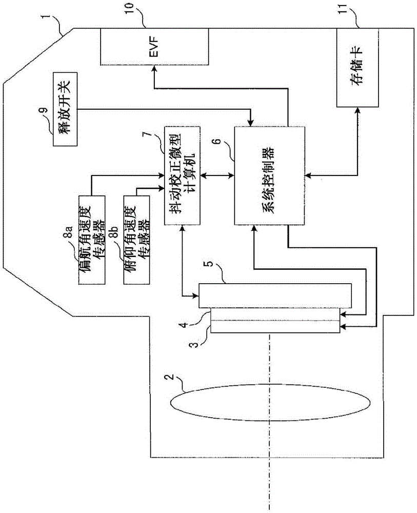
[0078] image 3 It is a diagram showing a configuration example of a camera including the image blur correction device according to the first embodiment of the present invention.

[0079] Such as image 3As shown, the camera 1 includes: an optical system 2, a focal plane shutter (hereinafter referred to simply as the shutter) 3, an imaging element 4, a drive unit 5, a system controller 6, a shake correction microcomputer 7, an angular velocity sensor 8, and a release SW (switch) 9. EVF (Electronic View Finder: Electronic View Finder) 10 and memory card 11 . In addition, the camera 1 is an example of an imaging device.

[0080] The optical system 2 forms a subject image. More specifically, the optical system 2 forms a light beam from the direction of the external optical axis on the imaging surface of the imaging element 4 as a subject image.

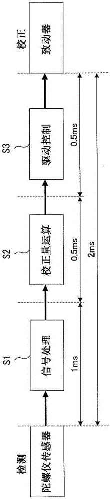
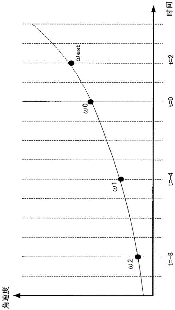
[0081] The shutter 3 opens and closes in front of the imaging element 4 under the control of the system controller 6 , thereby brin...

no. 2 Embodiment approach

[0112] A camera including the image shake correction device according to the second embodiment of the present invention differs from a camera including the image shake correction device according to the first embodiment in the structure and operation of the camera shake correction microcomputer. Therefore, in the description of the camera including the image blur correction device according to the present embodiment, the description will focus on this difference. In addition, in this embodiment, the same code|symbol is attached|subjected and demonstrated about the same component as the component demonstrated in 1st Embodiment.

[0113] The structure of the camera 1 including the image shake correction device of this embodiment image 3 The camera 1 shown has the same structure, so description is omitted here.

[0114] Figure 7 It is a diagram showing a configuration example of the camera shake correction microcomputer 7 included in the camera 1 including the image shake cor...

no. 3 Embodiment approach

[0129] The camera including the image shake correction device according to the third embodiment of the present invention is different from the camera including the image shake correction device according to the first embodiment in that it further includes an acceleration sensor and an accompanying shake correction microcomputer in terms of its structure and operation. different. Therefore, in the description of the camera including the image blur correction device according to the present embodiment, the description will focus on this difference. In addition, in this embodiment, the same code|symbol is attached|subjected and demonstrated about the same component as the component demonstrated in 1st Embodiment.

[0130] Figure 10 It is a diagram showing a configuration example of a camera including the image blur correction device of the present embodiment.


PUM


Abstract

This image blur correction device is provided with: a blur correction unit for correcting image blur by moving a lens included within an optical system in a perpendicular direction with respect to the optical axis, or by moving an imaging element over the imaging plane; a blur detection unit for detecting the amount of change in orientation of the imaging device; a holding unit for holding three or more amounts of change in orientation detected at different points in time; a prediction unit for calculating a predicted value of change in orientation subsequent to a predetermined time, on the basis of an approximation function based on temporal change of the amount of change in orientation, on the basis of three or more amounts of change in orientation; a blur level calculation unit for calculating an image blur level on the basis of the predicted value; and a drive control unit for calculating, on the basis of the image blur level, an amount of movement of the lens or the imaging element by the image blur correction unit.

Description

technical field [0001] The present invention relates to an image shake correction device that corrects image quality degradation caused by image shake caused by hand shake during photography, and an imaging device equipped with the image shake correction device. Background technique [0002] In recent years, cameras equipped with a hand-shake correction function have become popular. With this type of camera, even when the photographer is not particularly concerned about hand-shake during hand-held photography, it is possible to capture an image without image shake. [0003] In general, the correction performance of the hand-shake correction function of a camera is represented by the value of the shutter speed (exposure time) at which image shake can be corrected. This is using the shutter speed at which the effects of image shake caused by hand-shake start to appear in images taken without performing the hand-shake correction function (also called the hand-shake limit shutt...

Claims


Application Information

Patent Timeline
Patent Type & Authority Applications(China)
IPC IPC(8): G03B5/00H04N5/225H04N5/232
CPCG03B5/00G03B2205/0038H04N23/6812H04N23/687
Inventor 土屋仁司
Owner OM DIGITAL SOLUTIONS CORP
Why Eureka
Try Eureka