A clamp for the side of milling ear of universal joint fork

A universal joint fork and milling lug technology is applied in the field of the side fixture of the universal joint fork milling lug, which can solve the problems of inability to meet the requirements of high efficiency and speed, lack of positioning support, slow speed, etc., and achieves simple structure, good effect and high efficiency. Effect

Active Publication Date: 2017-07-07
XUCHANG YUANDONG DRIVE SHAFT +1
View PDF5 Cites 0 Cited by
  • Summary
  • Abstract
  • Description
  • Claims
  • Application Information

AI Technical Summary

Problems solved by technology

[0002] According to the design requirements of the universal joint yoke of the automobile transmission shaft, the inner and outer sides of the ear hole should be finished to meet its design function; milling cutter for processing; in order to improve the processing quality and efficiency of the workpiece, the inventor has specially developed a milling machine cutter head device that processes multiple faces at the same time to meet the needs; but the existing common three-jaw chuck is manual clamping, The speed is slow and lacks the necessary positioning support, which cannot meet the requirements of high efficiency and speed

Method used


Image

  • A clamp for the side of milling ear of universal joint fork
  • A clamp for the side of milling ear of universal joint fork
  • A clamp for the side of milling ear of universal joint fork

Examples


Embodiment 1

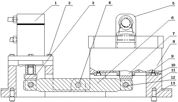
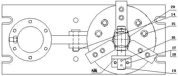
[0019] Such as figure 1 , figure 2 As shown, a universal joint fork milling ear side fixture, which includes hydraulic cylinder 1, hexagon bolt 2, hinge fork seat A3, pin B4, hinge fork seat B7, hydraulic three-jaw chuck 8, intermediate transition Disk 9, hexagon socket head screw A10, pin A12, positioning pin 13, split pin 14, hexagon socket head screw B15, cylindrical pin 16, hexagon socket head screw C17, hexagon socket head screw D18, the hydraulic cylinder 1 is fixed Set on the base 11, the hydraulic cylinder 1 and the base 11 are connected with hexagonal bolts 2, the power output end of the hydraulic cylinder 1 is connected to the connecting rod 6 through the hinge fork seat A3; the connecting rod 6 The middle section of the connecting rod 6 is hinged to the base 11 through the pin B4, one end of the connecting rod 6 is connected to the hydraulic cylinder 1 through the hinge fork seat A3, and the other end of the connecting rod 6 is connected to the intermediate transitio...

Embodiment 2

[0025] Such as figure 1 , figure 2 As shown, a universal joint fork milling ear side fixture, which includes a hydraulic cylinder 1, a hexagonal bolt 2, a hinge fork seat A3, a pin B4, a hinge fork seat B7, a hydraulic three-jaw chuck 8, and a middle transition Disk 9, hexagon socket stud A10, pin A12, positioning pin 13, split pin 14, hexagon socket stud B15, cylindrical pin 16, hexagon socket stud C17, hexagon socket stud D18, the hydraulic cylinder 1 is fixed Set on the base 11, the hydraulic cylinder 1 and the base 11 are connected with hexagonal bolts 2, the power output end of the hydraulic cylinder 1 is connected to the connecting rod 6 through the hinge fork seat A3; the connecting rod 6 The middle section of the connecting rod 6 is hinged to the base 11 through the pin B4, one end of the connecting rod 6 is connected to the hydraulic cylinder 1 through the hinge fork A3, and the other end of the connecting rod 6 is connected to the intermediate transition plate through...


PUM


Abstract

The invention relates to a universal joint fork lug side face milling clamp. The universal joint fork lug side face milling clamp comprises a hydraulic cylinder, a hexagon bolt, a hinge fork base A, a pin shaft B, a hinge fork base B, a hydraulic three-jaw chuck, a middle transition disc, an internal hexagonal column head screw A, a pin shaft A, a positioning pin, a cotter pin, an internal hexagonal column head screw B, a cylindrical pin, an internal hexagonal column head screw C and an internal hexagonal column head screw D. The output end of the hydraulic cylinder is connected with a connecting rod through the hinge fork base A. One end of the connecting rod is connected with the middle transition disc through the hinge fork base B. A positioning supporting plate is arranged on the chuck face of the hydraulic three-jaw chuck. The positioning supporting plate is in an L shape. A positioning hole is formed in a protrusion, perpendicular to the upper end face of the chuck, of the positioning supporting plate. The protrusion of the positioning supporting plate is perpendicular to one disc of the chuck. The positioning hole in the protrusion of the positioning supporting plate is provided with a core rod matched with the positioning hole. On the whole, the universal joint fork lug side face milling clamp has the advantages of being fast in positioning, high in precision, portable to assemble and disassemble, safe and rapid.

Description

Technical field [0001] The invention belongs to the field of mechanical manufacturing equipment and technology, and in particular relates to a milling machine clamp, in particular to a universal joint fork milling ear side clamp. Background technique [0002] According to the design requirements of the universal joint fork of the automobile transmission shaft, the inner and outer sides of the ear hole should be finished to meet its design function; during the side processing, the bottom of the universal joint fork needs to be positioned and clamped, and then the disc The milling cutter is used for processing; in order to improve the processing quality and efficiency of the workpiece, the inventor has specially developed a milling machine tool head device that processes multiple faces at the same time to meet the needs; but the existing ordinary three-jaw chuck is manually clamped, The speed is slow and lacks the necessary positioning support, which cannot meet the requirements of...

Claims


Application Information

Patent Timeline
Patent Type & Authority Patents(China)
IPC IPC(8): B23Q3/08B23C3/00B23C9/00B23C5/08
CPCB23C3/00B23C5/08B23C9/005B23C2270/08B23Q3/082B23Q2703/04
Inventor 李来成马喜岭陈云升李建勋尚国生周永川张峰韩利周建喜张俊华张鹏超张庆科雷务然顾鲜美齐瑞晓李磊唐记敏柴二帅姚晋业刘金檑李松建
Owner XUCHANG YUANDONG DRIVE SHAFT
Why Eureka
Try Eureka