
Measurement device

A measurement device and particle detection technology, applied in the direction of measurement devices, suspension and porous material analysis, instruments, etc., can solve the problems of inability to correctly diagnose the pollution state, air bubble pollution, etc., achieve simple measurement of pollution degree, and prevent mismeasurement Effect

Active Publication Date: 2016-03-09
YAMASHIN FILTER CORP
View PDF9 Cites 0 Cited by
  • Summary
  • Abstract
  • Description
  • Claims
  • Application Information

AI Technical Summary

Problems solved by technology

[0006] In the invention described in Patent Document 1, if air bubbles or the like are contained in the hydraulic oil, the air bubbles may be misdetected as contamination, and the contamination state may not be correctly diagnosed.

Method used


Image

  • Measurement device
  • Measurement device
  • Measurement device

Examples


Embodiment Construction

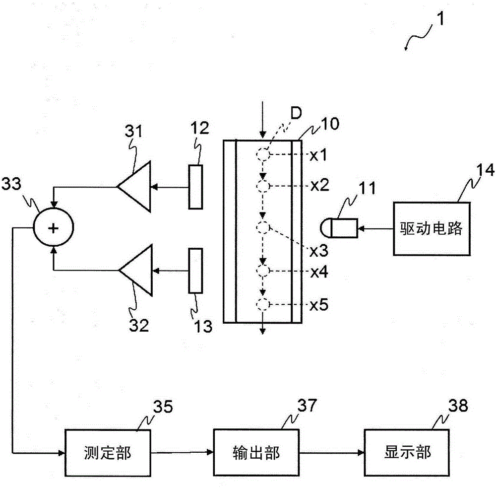
[0045] Hereinafter, embodiments of the present invention will be described in detail with reference to the drawings. figure 1 It is a figure which shows the schematic diagram of the pollution degree measuring apparatus 1. The pollution level measuring device 1 is installed at a desired position of a device that uses liquid to perform a desired operation, such as construction equipment and hydraulic equipment.

[0046] At least a part of the measurement channel 10 through which liquid such as oil and water to be measured flows is formed of a translucent material. That is, the measurement channel 10 may be formed entirely of a light-transmitting material, or a window for introducing and exporting light may be formed in a part.

[0047] A light emitting unit (for example, LED) 11 for irradiating light into the measurement flow channel 10 from one side is disposed on a portion of the measurement flow channel 10 formed of a light-transmitting material. On the side opposite to the...


PUM


Abstract

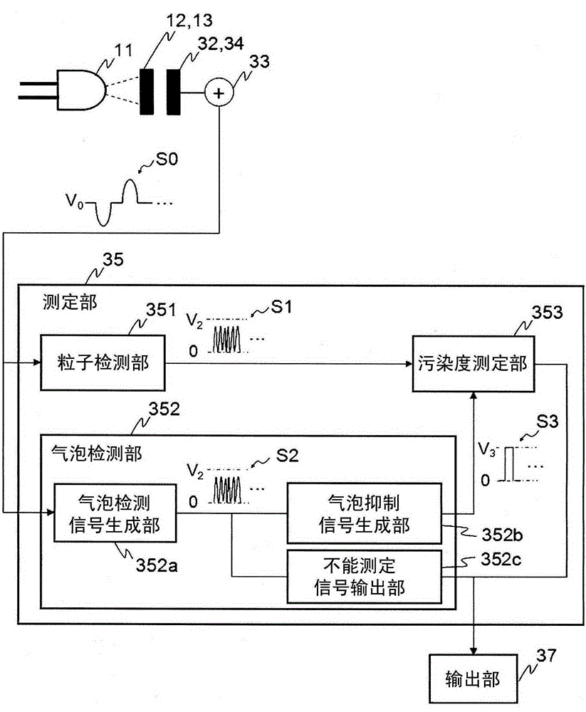
The invention provides a measurement device which can prevent an error measurement resulted from bubbles and simply measure the degree of pollution. On the basis of a particle detection signal and an air bulb detection signal, a signal for measuring the degree of pollution of a liquid is generated, wherein the particle detection signal is a continuous signal which is generated thorugh amplification of a continuous electrical signal converted by a light-receiving section at first multiplying power, and the air bubble detection section is a continous signal generated by amplification of a continous electrical signal converted by the light receiving section at second multiplying power less than the multiplying power.

Description

technical field [0001] The present invention relates to assay devices. Background technique [0002] Patent Document 1 discloses a hydraulic oil contamination state diagnostic device, which uses a mini pump to circulate hydraulic oil at a nearly constant speed in a flow channel of a microcell made of a transparent glass material. The laser light irradiated from the light emitting element installed at the position sandwiching the flow path from the left and right transmits the hydraulic oil in the flow path, and is received by the light receiving element installed at the position sandwiching the flow path from the left and right sides , and output a detection signal corresponding to the amount of light received from the light receiving element to the controller. [0003] prior art literature [0004] patent documents [0005] Patent Document 1: Japanese Patent Laid-Open No. 2001-221793 [0006] In the invention described in Patent Document 1, if air bubbles or the like ar...

Claims


Application Information

Patent Timeline
Patent Type & Authority Applications(China)
IPC IPC(8): G01N15/06
CPCG01N15/1429G01N15/1456G01N33/2835
Inventor 石塚雅规
Owner YAMASHIN FILTER CORP
Learn More