
Tuning device and method for magnetic resonance imaging system radio frequency coil

A magnetic resonance imaging and radio frequency coil technology, which is applied in the directions of magnetic resonance measurement, measurement device, measurement of magnetic variables, etc., can solve the problem of reducing the working frequency of the radio frequency coil, the mismatch between the working frequency of the receiving coil and the magnetic field strength, and changing the impedance of the radio frequency transmitting coil. and other problems to achieve the effect of frequency tuning

Active Publication Date: 2016-03-09
NEUSOFT MEDICAL SYST CO LTD
View PDF6 Cites 8 Cited by
  • Summary
  • Abstract
  • Description
  • Claims
  • Application Information

AI Technical Summary

Problems solved by technology

[0004] However, when subjects of different sizes are moved into the magnet cavity by the patient bed, or the position of the same subject in the magnet changes, it will cause capacitance effects
This capacitive effect will not only change the impedance of the RF transmitting coil, but also change the frequency of the receiving coil, so that the operating frequency of the receiving coil does not match the magnetic field strength, the operating frequency of the RF coil decreases and the quality factor decreases, resulting in image SNR reduction

Method used


Image

  • Tuning device and method for magnetic resonance imaging system radio frequency coil
  • Tuning device and method for magnetic resonance imaging system radio frequency coil
  • Tuning device and method for magnetic resonance imaging system radio frequency coil

Examples


Embodiment Construction

[0021] The exemplary embodiments will be described in detail here, and examples thereof are shown in the accompanying drawings. When the following description refers to the accompanying drawings, unless otherwise indicated, the same numbers in different drawings represent the same or similar elements. The implementation manners described in the following exemplary embodiments do not represent all implementation manners consistent with the present application. Rather, they are merely examples of devices and methods consistent with some aspects of the application as detailed in the appended claims.

[0022] The terms used in this application are only for the purpose of describing specific embodiments and are not intended to limit the application. The singular forms of "a", "said" and "the" used in this application and the appended claims are also intended to include plural forms, unless the context clearly indicates other meanings. It should also be understood that the term "and / ...


PUM


Abstract

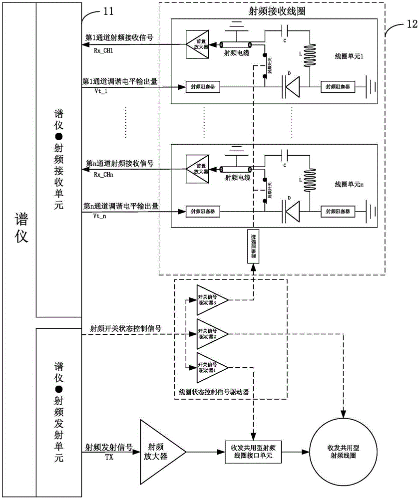
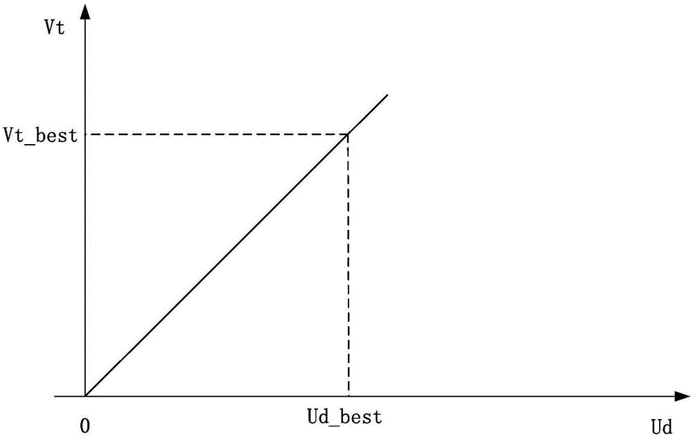
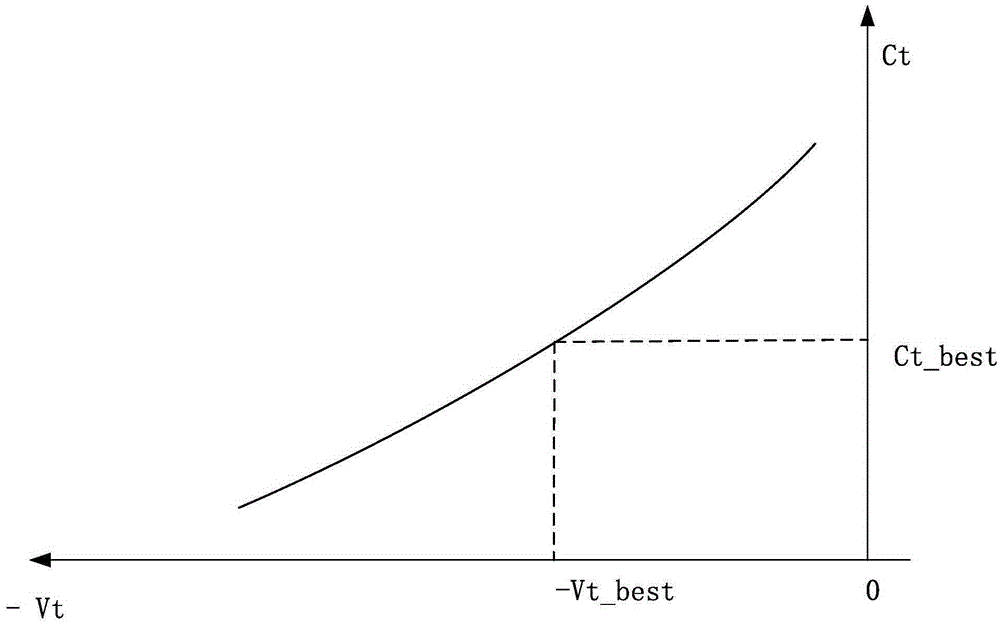
The invention provides a tuning device and method for a magnetic resonance imaging system radio frequency coil. The device comprises a spectrometer and a radio frequency receiving coil, wherein the radio frequency receiving coil comprises multiple coil units, each coil unit of the multiple coil units comprises a variable capacitive reactance device and a radio frequency obturator, each variable capacitive reactance device is bunched into a resonance circuit of the corresponding coil unit, and coil tuning level input to each coil unit by the spectrometer is applied to the corresponding variable capacitive reactance device through the corresponding radio frequency obturator, so as to regulate the capacitance of the corresponding resonance circuit; the spectrometer is used for receiving a free induction decay signal generated by each coil unit in the radio frequency receiving coil due to magnetic resonance, finding maximum values of the free induction decay signals on the basis of iteration traversal of a tuning evaluation function, and applying the tuning level corresponding to the maximum values to two ends of the variable capacitive reactance devices in the resonance circuits. By adopting the technical scheme, tuning of the magnetic resonance imaging oil can be quickly realized.

Description

Technical field [0001] This application relates to the technical field of medical equipment, and in particular to a tuning device and method for a radio frequency coil of a magnetic resonance imaging system. Background technique [0002] The radio frequency coil is one of the key components of the magnetic resonance imaging system. It is responsible for the transmission of radio frequency signals and the reception of magnetic resonance signals, and determines the imaging quality of the entire imaging equipment. The radio frequency coil of the magnetic resonance imaging system can be divided into a transmitting coil and a receiving coil according to functions. The transmitting coil is usually a radio frequency coil integrated with the transceiver, which performs both the transmitting function of radio frequency signals and the receiving function of magnetic resonance signals, while the receiving coil only performs the receiving function of magnetic resonance signals. [0003] In th...

Claims


Application Information

Patent Timeline
IPC IPC(8): G01R33/36
CPCG01R33/3628
Inventor 史建华胡红兵谷会东李海泉吴林王宏伟王艳左红孙容
Owner NEUSOFT MEDICAL SYST CO LTD
Learn More