A Directional Coupler Based on Transformer

A directional coupler and transformer technology, applied in waveguide-type devices, circuits, connecting devices, etc., can solve the problems of directional couplers with small insertion loss area, the length can not meet the requirements of integration, and improve the complexity of the system, and achieve the scope of application. Wide, low cost, good directional effect

Inactive Publication Date: 2016-03-02
PEKING UNIV
View PDF4 Cites 0 Cited by
  • Summary
  • Abstract
  • Description
  • Claims
  • Application Information

AI Technical Summary

Problems solved by technology

[0004] For traditional directional couplers, the use of ceramic passive components is the most widely used method, but its size limitation and high cost hinder its application in highly integrated and low power consumption environments
The document "Apassivecirculator with high isolation using directional coupler for RFID, inIEEEMTT-SInt. isolation, but its length is far from meeting the requirements of integration
The document "ACMOSpoweramplifierwithintegratedpassive-devicespiral-shapeddirectionalcouplerformobileUHFRFIDreader, IEEETrans. However, it needs to be packaged with the CMOS transceiver system using system packaging technology, which increases the complexity of the system and increases the cost
The document "Acompact highly reconfigurable CMOSMMIC directionalcoupler, IEEETrans.Microw.TheoryTech., vol.56, no.2, pp.305-319, Feb.2008" discloses an active CMOS directional coupler based on lumped LC elements, however the active device Additional power dissipation will be required, and the lumped element will also take up a lot of area
[0005] In the prior art, there is no directional coupler that is suitable for various application environments and process conditions, has excellent isolation and insertion loss, and has a very small area, especially the directional coupler based on the concept of transformer and can be used for on-chip integration of CMOS technology. source directional coupler

Method used


Image

  • A Directional Coupler Based on Transformer
  • A Directional Coupler Based on Transformer
  • A Directional Coupler Based on Transformer

Examples


Embodiment Construction

[0037] The present invention will be described in detail below through the embodiments and in conjunction with the accompanying drawings.

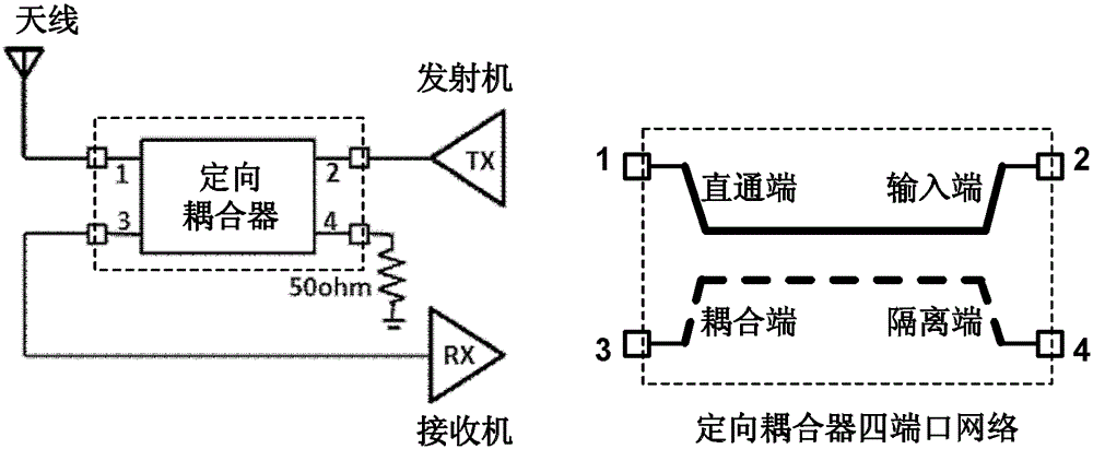
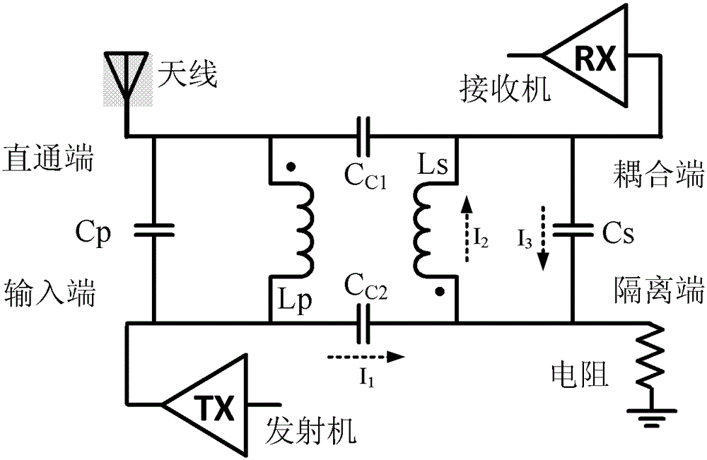
[0038] The transformer-based directional coupler of this embodiment is implemented on a standard CMOS process or a BiCMOS process, image 3 is the schematic diagram of the directional coupler. As shown in the figure, the directional coupler includes two coupled coils Lp and Ls, the two ends of the coil Lp are respectively used as the input end and the through end, and the two ends of the coil Ls are respectively used as the coupling end and the isolation end. An adjustable capacitor array Cp is provided between the input terminal and the through terminal for frequency tuning; an adjustable capacitor array Cs is provided between the coupling terminal and the isolation terminal for isolation tuning. Cp and Cs can make the directional coupler obtain the best performance under the application conditions of different input impedance or process...


PUM


Abstract

The invention provides a transformer-based directional coupler. The transformer-based directional coupler comprises a first coil, a second coil, two adjustable capacitors and two crossover capacitors, wherein both ends of the first coil respectively serve as an input end and a shoot-through end; the second coil, together with the first coil, forms a transformer structure, and both ends of the second coil respectively serve as a coupling end and an isolation end; one of the adjustable capacitors is connected with the input end of the shoot-through end, and the other one of the adjustable capacitors are connected with the coupling end and the isolation end; and one of the crossover capacitors is connected with the shoot-through end and the coupling end, and the other one of the crossover capacitors is connected with the input end of the isolation end. The transformer-based directional coupler can be applied to multiple application occasions and process environments, and especially can be applied to on-chip integration by using the CMOS technology, thereby substantially reducing complexity of the system design and effectively improving performance of the system.

Description

technical field [0001] The invention belongs to the technical field of radio frequency / microwave integrated circuits, and relates to a directional coupler, in particular to a transformer-based directional coupler. Background technique [0002] Directional Coupler (DirectionalCoupler) is a widely used radio frequency / microwave component, and is widely used in transceiver systems where the uplink and downlink are in the same frequency band. The principle of directional coupler applied to transceiver system is as follows: figure 1 As shown, "Input" (Input) is connected to the transmitter output (TX), "Direct" (Direct) is connected to the antenna (Antenna), "Coupled" (Coupled) is connected to the receiver input (RX), "Isolation Terminal" (Isolated) is connected to the matching resistor (Res). Among them, the loss between the input end and the through end is "Insertion Loss", the loss between the input end and the coupling end is "Coupling", and the loss between the through end...

Claims


Application Information

Patent Timeline
Patent Type & Authority Patents(China)
IPC IPC(8): H01P5/18
Inventor 叶乐廖毓郭盈廖怀林黄如
Owner PEKING UNIV
Why Eureka
Try Eureka