Decoration effect displaying method and system of cubic room

An effect display and cube technology, applied in image data processing, instruments, etc., can solve problems such as misleading decoration effects, unavoidable house size errors, and inability to view decoration effects, etc. It achieves strong real-time performance, avoids house type size errors, and is easy to operate Effect

Active Publication Date: 2016-03-09
FUJIAN TQ DIGITAL
View PDF3 Cites 29 Cited by
  • Summary
  • Abstract
  • Description
  • Claims
  • Application Information

AI Technical Summary

Problems solved by technology

The user needs to import the floor plan to generate a 3D house model. The floor plan is mostly obtained after the house is purchased, and the user cannot check the decoration effect before buying the house; even if the user can check the decoration effect before buying the house, it cannot be avoided. The existence of house size errors caused by errors, thus misleading the actual decoration effect

Method used


Image

  • Decoration effect displaying method and system of cubic room
  • Decoration effect displaying method and system of cubic room

Examples


Embodiment 1

[0064] Please refer to figure 1 , Embodiment 1 of the present invention is:

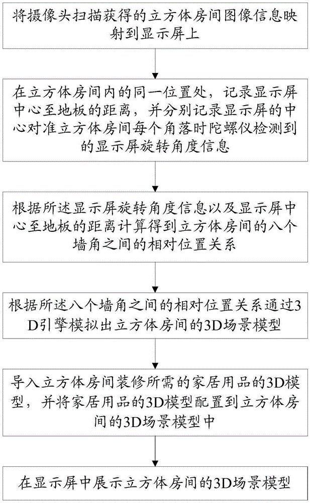
[0065] A method for displaying the decoration effect of a cube room,

[0066] Map the cubic room image information obtained by the camera scanning to the display screen;

[0067] At the same position in the cubic room, record the distance from the center of the display screen to the floor, and record the rotation angle information of the display screen detected by the gyroscope when the center of the display screen is aligned with each corner of the cubic room;

[0068] According to the display screen rotation angle information and the distance from the center of the display screen to the floor, the relative positional relationship between the eight corners of the cubic room is calculated, specifically:

[0069] At the same position in the cubic room, according to the rotation angle information of the display screen, eight rays starting from the center of the display screen and passing through the ...

Embodiment 2

[0099] Please refer to figure 2 , the second embodiment of the present invention is:

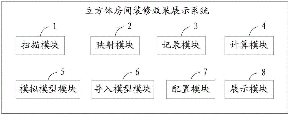
[0100] A cube room decoration effect display system, including a scanning module 1, a mapping module 2, a recording module 3, a calculation module 4, a simulation model module 5, an import model module 6, a configuration module 7, and a display module 8,

[0101] Scanning module 1, used for camera scanning to obtain cube room image information;

[0102] The mapping module 2 is used to map the cubic room image information obtained by the camera scanning onto the display screen;

[0103] The recording module 3 is used to record the distance from the center of the display screen to the floor, and record the rotation angle information of the display screen detected by the gyroscope when the center of the display screen is aligned with each corner of the cube room;

[0104] The calculation module 4 calculates the relative positional relationship between the eight corners of the cube room accor...


PUM


Abstract

The invention provides a decoration effect displaying method and system of a cubic room. The method comprises: image information, obtained by scanning by a camera, of a cubic room is mapped to a display screen; a distance between the center of the display screen to a floor is recorded at a same position inside the cubic room, display screen rotation angle information that is detected by a gyroscope when the center of the display screen is aligned at each corner of the cubic room is recorded respectively; according to the display screen rotation angle information as well as the distance between the center of the display screen and the floor, calculation is carried out to obtain relative position relations between the eight corners of the cubic room; on the basis of the relative position relations of the eight corners, a 3D scene model of the cubic room is simulated by using a 3D engine; a 3D model of a household item needed by decoration of the cubic room is introduced and is configured into the 3D scene model of the cubic room; and the 3D scene model of the cubic room is displayed on the display screen. With the method and system, a room dimension can be measured on site and a room decoration effect can be displayed.

Description

technical field [0001] The invention relates to the technical field of house decoration, in particular to a method and system for displaying decoration effects of a cube room. Background technique [0002] At present, the common techniques for browsing room decoration effects are that professionals use special image or processing software in computer software, or decoration design software to design and produce, and finally display them in the form of 2D photos or 3D virtual display, so as to view the decoration effect . The characteristic of these technical solutions is that the user can only see the relatively fine room decoration reference effect after purchasing the house, and cannot view the decoration effect on the spot to assist the house purchase decision. [0003] The Chinese invention patent with the publication number CN104778756A discloses a smart home decoration design system, including a house type generation module, three viewing angle presentation modules, a...

Claims


Application Information

Patent Timeline
IPC IPC(8): G06T19/00
CPCG06T19/003
Inventor 郑朝鑫毛建琦叶仲雯吴拥民陈宏展刘德建
Owner FUJIAN TQ DIGITAL
Why Eureka
Try Eureka