A key switch device supported by sheet metal scissor feet with elastic hook limit structure

A technology of elastic hook and limit structure, which is applied to electric switches, contact operating mechanisms, electrical components, etc., can solve the problems of low injection precision, low stamping precision, injection defects, and low-profile design, and achieve low-profile, The effect of reducing defect rate and high reliability

Active Publication Date: 2019-02-05
陈峰
View PDF4 Cites 1 Cited by
  • Summary
  • Abstract
  • Description
  • Claims
  • Application Information

AI Technical Summary

Problems solved by technology

[0014] Since the birth of the keyboard, the key cap 1 of the notebook keyboard has been provided with a plastic elastic limit structure, see figure 2 --1 to figure 2 --5. When installing the keycap 1, first install the keycap sliding part 3 on the upper sliding part 6 of the scissors, and then rotate the keycap downward. During the pressing process, the two pieces of the keycap rotating part 2 are short and thick The plastic elastic limit structure needs to produce a deformation of about 0.15mm on one side---about 6 degrees of rotation. The width B1 of the two short and thick plastic elastic limit structures is about 0.7mm, and the length H1 is about 1.6mm. B1 / H1=0.4375, because plastic is a plastic material, the short and thick plastic elastic limit structure has poor elasticity, low strength, and small limit interference. In addition, the notebook keyboard is getting thinner and thinner, and the two pieces of the keycap rotating part 2 The short and thick plastic elastic limit structure (H1 size) limits the design of the low height of the keycap 1. At the same time, due to the influence of injection molding defects, the mold of the two short and thick plastic elastic limit structures of the keycap rotating part 2 needs to be tilted. Pulling structure, etc. The two short and thick plastic elastic limit structures of the keycap rotating part 2 have a high defect rate when leaving the factory
[0015] 1. After the keycap 1 of the notebook keyboard leaves the factory, the problem of falling off is very prominent. The problem of key drop and switch contact failure of the notebook keyboard are the two most prominent problems that need to be solved in the notebook keyboard at present.
[0016] 2. The plastic elastic limit structure of the key cap 1 of the notebook keyboard is affected by injection defects.
[0017] 3. The fit interference of the short and thick plastic elastic limit structure of the keycap 1 of the notebook keyboard is 0.15mm on one side. When it is too large, it is prone to the hidden danger of fracture failure and buried fracture failure of the two short and thick plastic elastic limit structures of the keycap rotating part 2
[0018] 4. Two short and thick plastic elastic limit structures have poor elasticity and low strength
[0019] 5. The precision of injection molding is lower than the stamping precision of sheet metal. Precision injection molding—the tolerance of small-sized structural injection molded parts is 0.08mm. Linear size stamping——the stamping accuracy of sheet metal is 0.026mm, and the stamping and bending accuracy of sheet metal is 0.5 degrees.
[0020] 6. Thinning the keycap, it is bound to be shortened--short and thick plastic elastic limit structure, the short and thick plastic elastic limit structure is shortened, resulting in the lower limit of the elasticity of the short and thick plastic elastic limit structure, which limits the further low height of the keycap design

Method used


Image

  • A key switch device supported by sheet metal scissor feet with elastic hook limit structure
  • A key switch device supported by sheet metal scissor feet with elastic hook limit structure
  • A key switch device supported by sheet metal scissor feet with elastic hook limit structure

Examples


Embodiment 1

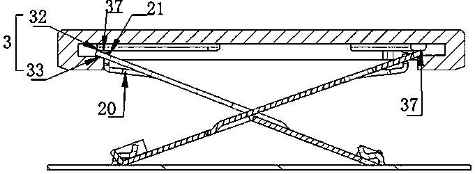
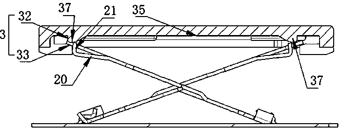
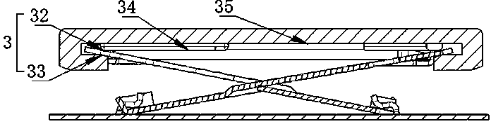
[0096] Such as image 3 --- Figure 48 As shown, a key switch device supported by a sheet metal scissors foot with an elastic hook limit structure of the present invention includes a keycap, a reset element, a switch circuit with a switch, a support plate with a matching part, and scissors with an upper and lower matching part. The foot support, the scissor foot support is respectively connected with the keycap and the support plate through the upper and lower matching parts to rotate or slide, and the scissor foot support forms a synchronous linkage support structure through the transmission of force between each other to ensure that the keycap is parallel to the support plate. Lifting movement, the scissors support 16 is stamped and formed on the metal plate surface; the scissors support 16 is formed with elastic sheet metal elastic arms 20; the scissors support 16 has a stamped and formed scissors anti-off structure;

[0097] The key cap 1 is provided with a key limiting b...

Embodiment 2

[0122] see Figure 18 , Figure 19 , the scissors lower plane 17 of the metal inner scissors foot 28 is located on the outside of the scissors upper plane 19, the scissors lower plane 17 of the metal outer scissors foot 31 is respectively located at the inner side and the lower side of the scissors upper plane 19, and the scissors lower plane 17. The upper plane 19 of the scissors is connected by a length bending edge 41 , and the length bending edge 41 is along the length direction of the scissors leg 23 .

[0123] The inner scissors supporting part 18 of the metal inner scissors foot 28 located on the outer side of the scissors upper plane 19 is perpendicular to the length direction of the scissors arm 23, and the metal outer scissors foot 31 has an end surface extending plate 43, and the end surface extends the plate surface The cantilever end face of 43 is perpendicular to the length direction of scissors foot arm 23.

[0124] There is an inner reinforcing flange 42 on t...

Embodiment 3

[0132] Such as Figure 23 , Figure 24 , Figure 25 , Figure 26 1. Between the left and right end surfaces of the sheet metal scissors support, and near the upper end surface of the sheet metal scissors support, there is a cantilever notch through hole 20a that runs through the sheet metal scissors support plate, and at the left end of the cantilever notch through hole 20a There is a sheet metal elastic arm 20 extending to the other end face on the face or the right end face.

[0133] Such as Figure 23 , Figure 24 1. The sheet metal elastic arm 20 is a cantilever, and the scissors anti-off structure is located at the end of the sheet metal elastic arm 20 cantilever.

[0134] Such as Figure 25 , Figure 26 1. The sheet metal elastic arm 20 is rigidly connected to the left and right end faces of the sheet metal scissors foot support, and the scissors anti-off structure is located on the sheet metal elastic arm 20, but it is best to locate the scissors anti-off structu...


PUM


Abstract

A key switch device supported by sheet metal scissor feet with a cantilever elastic hook limit structure of the present invention is characterized in that: the scissor foot support 16 is stamped and formed on the metal plate surface; the scissor foot support 16 is formed with elasticity The sheet metal elastic cantilever 20, the scissors foot support 16 has a stamped and formed scissors anti-off structure; the key cap 1 is provided with a key limit boss 45, and the mutually supporting scissors feet support 16 passes through the scissors anti-off structure Cooperate with the key limiting boss 45 of the key cap 1 to prevent the key from coming out or limit the key cap 1 to the upper limit position; the key switch device of the metal scissor foot structure can be widely used in computer keyboards, palmtop computers, various A type of embedded keyboard and a key switch device for keystroke operation. The strength and structural rigidity of the supporting structure of the scissor feet are greatly improved, and the metal scissor feet realizes ultra-light, ultra-thin and further realizes the miniaturization of the key device.

Description

[0001] Priority Statement: [0002] Claims 1, 2, 7--9 of the present invention require the priority of claims 42-46 and the corresponding embodiments of the invention patent application with the application number 2015103291395 submitted to the China National Intellectual Property Office on June 15, 2015; [0003] Claim 1 and claim 10 of the present invention claim the priority of claim 1 and the corresponding embodiments of the invention patent application with application number 2015101574277 submitted to China National Intellectual Property Office on April 5, 2015; [0004] Claim 3 of the present invention, claim 1 plus claim 10 claim the priority of claim 49 and the corresponding embodiments of the invention patent application with application number 2014104821017 submitted to the China National Intellectual Property Office on September 21, 2014; [0005] Claim 4 of the present invention, claim 1 plus claim 10 claim the priority of claim 49 and the corresponding embodiments ...

Claims


Application Information

Patent Timeline
Patent Type & Authority Patents(China)
IPC IPC(8): H01H3/12H01H13/22
CPCH01H3/125H01H13/22
Inventor 陈峰
Owner 陈峰
Why Eureka
Try Eureka