
Outdoor short-wave antenna mounting method

A technology of short-wave antenna and installation method, which is applied in the direction of antenna support/installation device, etc., and can solve the problems of low safety of installation operation, unfavorable installation and debugging, etc.

Active Publication Date: 2016-03-09
SHENZHEN DINGYI PRECISION HARDWARE
View PDF3 Cites 0 Cited by
  • Summary
  • Abstract
  • Description
  • Claims
  • Application Information

AI Technical Summary

Problems solved by technology

[0005] The purpose of the present invention is to provide a method for installing an outdoor short-wave antenna to solve the problem that when installing an outdoor short-wave antenna, since the installation height of the antenna vibrator layer is relatively high, the safety of the installation operation is likely to be low, and it is not easy to solve the problem. Helpful for installation and debugging

Method used


Image

  • Outdoor short-wave antenna mounting method
  • Outdoor short-wave antenna mounting method
  • Outdoor short-wave antenna mounting method

Examples


Embodiment Construction

[0037] The technical solutions of the present invention will be clearly and completely described below in conjunction with the accompanying drawings. Apparently, the described embodiments are some of the embodiments of the present invention, but not all of them. Based on the embodiments of the present invention, all other embodiments obtained by persons of ordinary skill in the art without making creative efforts belong to the protection scope of the present invention.

[0038] In the description of the present invention, it should be noted that the terms "center", "upper", "lower", "left", "right", "vertical", "horizontal", "inner", "outer" etc. The indicated orientation or positional relationship is based on the orientation or positional relationship shown in the drawings, and is only for the convenience of describing the present invention and simplifying the description, rather than indicating or implying that the referred device or element must have a specific orientation, ...


PUM


Abstract

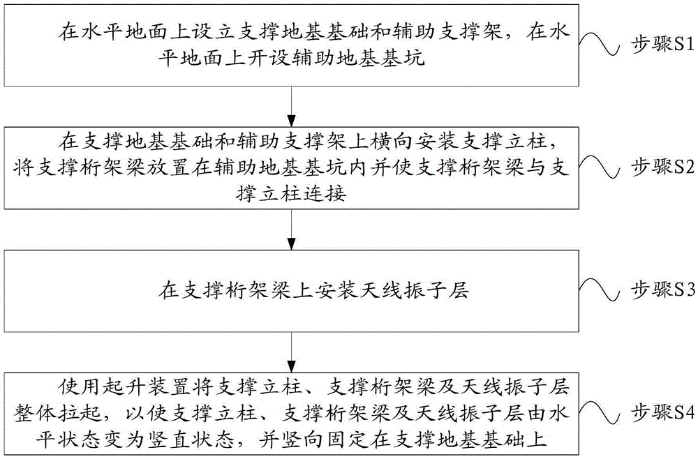
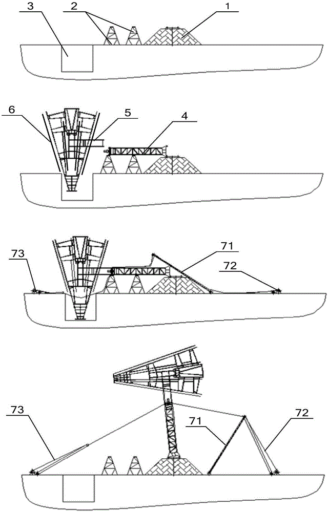
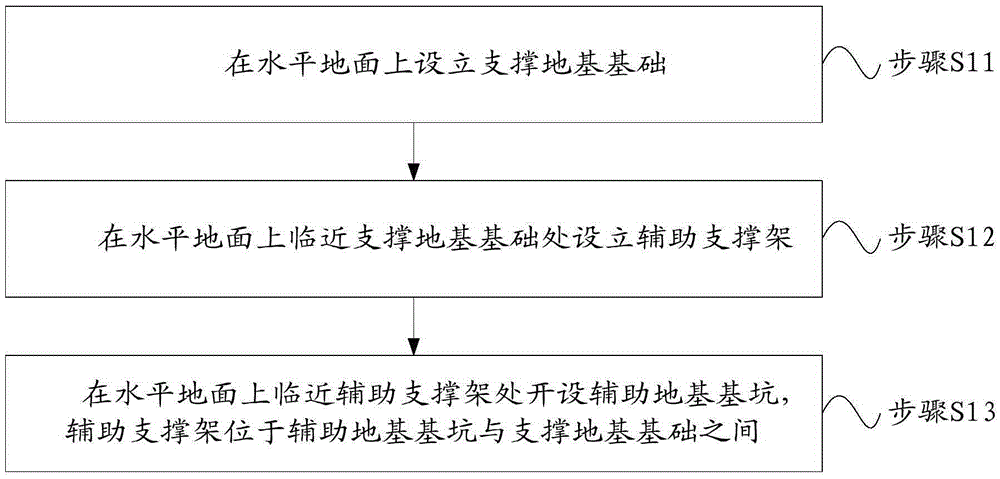
The invention discloses an outdoor short-wave antenna mounting method, relates to the technical field of antennae, and aims to solve the problems of relatively low safety in mounting operation and non-favorability for mounting and debugging caused by the fact that the mounting operation height of an antenna oscillator layer is relatively high in a mounting process of an outdoor short-wave antenna. The outdoor short-wave antenna mounting method comprises: establishing a supporting foundation and an auxiliary supporting frame on the horizontal ground, and forming an auxiliary foundation ditch; transversely mounting supporting stand columns on the supporting foundation and the auxiliary supporting frame, putting a supporting truss beam into the auxiliary foundation pitch, and enabling the supporting truss beam to be connected with the supporting stand columns; mounting the antenna oscillator layer on the supporting truss beam; and integrally pulling up the supporting stand columns, the supporting truss beam and the antenna oscillator layer by using a hoisting apparatus to change the supporting stand columns, the supporting truss beam and the antenna oscillator layer from a horizontal state to a vertical state, and vertically fixing the integral supporting stand columns, the supporting truss beam and the antenna oscillator layer to the supporting foundation. The present invention is applicable to outdoor short wave antenna installation.The outdoor short-wave antenna mounting method is mainly applied to the mounting of the outdoor short-wave antenna.

Description

technical field [0001] The invention relates to the technical field of antennas, in particular to an installation method of an outdoor short-wave antenna. Background technique [0002] At present, the domestic traditional outdoor short-wave large-scale antenna system is mainly based on the broadband curtain antenna. The broadband curtain antenna is an antenna array composed of multi-layer full-wave or half-wave dipoles. Its horizontal pattern is controlled by the number of array element antennas in each layer, and the vertical pattern is controlled by the number of layers of array element antennas and the lowest layer of antennas. Ground clearance control. Because the short-wave antenna has the advantages of wide frequency range, high power, and long propagation distance, it is widely used and is one of the important means of modern long-distance radio communication. [0003] Wherein, the outdoor short-wave antenna in the prior art generally includes: a support column at t...

Claims


Application Information

Patent Timeline
Patent Type & Authority Applications(China)
IPC IPC(8): H01Q1/12
CPCH01Q1/12
Inventor 张少林杨军
Owner SHENZHEN DINGYI PRECISION HARDWARE
Learn More