
Positioning device and installation method of fairing separation component support

A technology for separating components and positioning devices, applied in workpiece clamping devices, offensive equipment, weapon types, etc., can solve problems such as low assembly efficiency, low work efficiency, and large measurement errors, and achieve improved assembly efficiency, high positioning efficiency, and The effect of accurate positioning

Active Publication Date: 2021-09-03
TIANJIN ISTAR-SPACE TECH CO LTD
View PDF8 Cites 0 Cited by
  • Summary
  • Abstract
  • Description
  • Claims
  • Application Information

AI Technical Summary

Problems solved by technology

[0005] The purpose of the present invention is to provide a positioning device for the separation component support of the fairing to solve the problem in the prior art that the separation component support is positioned by manual measurement, and the measurement error is large; the work efficiency is low, and the separation Technical problem of low assembly efficiency of component support
[0006] The purpose of the present invention is to provide a method for installing the positioning device of the separation component support of the fairing, so as to solve the technical problems in the prior art that the support of the separation component is positioned by manual measurement and the assembly efficiency is low

Method used


Image

  • Positioning device and installation method of fairing separation component support
  • Positioning device and installation method of fairing separation component support
  • Positioning device and installation method of fairing separation component support

Examples


Embodiment Construction

[0056] It should be noted that, in the case of no conflict, the embodiments of the present invention and the features in the embodiments can be combined with each other.

[0057] In describing the present invention, it should be understood that the terms "center", "longitudinal", "transverse", "upper", "lower", "front", "rear", "left", "right", " The orientations or positional relationships indicated by "vertical", "horizontal", "top", "bottom", "inner" and "outer" are based on the orientations or positional relationships shown in the drawings, and are only for the convenience of describing the present invention and Simplified descriptions, rather than indicating or implying that the device or element referred to must have a particular orientation, be constructed and operate in a particular orientation, and thus should not be construed as limiting the invention. In addition, the terms "first", "second", etc. are used for descriptive purposes only, and should not be understood ...


PUM


Abstract

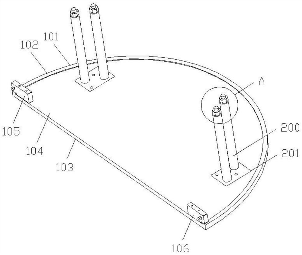
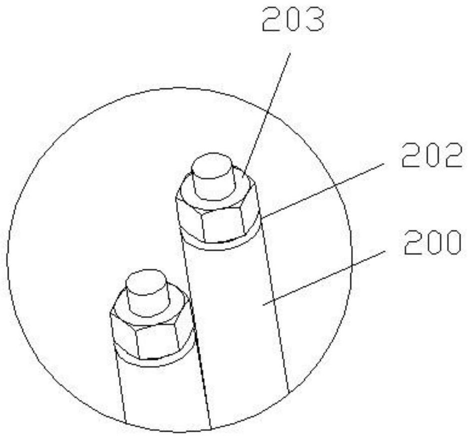
The invention discloses a positioning device for a separation assembly support of a fairing and an installation method thereof, and belongs to the technical field of positioning accessories of a fairing. The positioning device of the fairing separation assembly support includes a limit plate and a limit post; the limit plate is connected to the rear end frame of the fairing, and the limit plate can limit the end face position of the rear end frame; the limit post is detachably connected to the limit on the plate; the limit post is connected to the support of the separation assembly, so that the outer surface of the support of the separation assembly is attached to the inner skin of the fairing. The method solves the technical problems in the prior art that manual measurement is used to position the support of the separation component, and the measurement error is large; the work efficiency is low, and the assembly efficiency of the support of the separation component is low. The present invention limits the position of the rear end frame of the fairing through the limit plate, and positions the support of the separation assembly through the limit column on the limit plate, so that the positioning position of the support of the separation assembly is accurate, the positioning efficiency is high, and the separation assembly is improved. Efficiency of assembly between mounts and fairings.

Description

technical field [0001] The invention relates to the technical field of fairing positioning accessories, in particular to a positioning device and an installation method for a separating component support of a fairing. Background technique [0002] The satellite fairing of the launch vehicle generally adopts the separation spring to provide the impulse to realize the separation of the fairing, so as to ensure that the satellite enters the orbit according to the established procedure. The separation assembly support is the main part for the positioning and loading of the separation spring of the fairing. The position accuracy of the separation assembly support will affect the position accuracy of the separation spring, thereby affecting the separation of the fairing according to the program. [0003] In the prior art, installing the support of the separation component on the inner skin of the fairing requires the operator to use a measuring stick to measure the size on the fai...

Claims


Application Information

Patent Timeline
Patent Type & Authority Patents(China)
IPC IPC(8): B25B11/02B64G1/10F42B15/36
CPCB25B11/02B64G1/10F42B15/36
Inventor 丁常方郭浩麻永帅张鹏刘含洋王志勇刘千
Owner TIANJIN ISTAR-SPACE TECH CO LTD
Learn More