High-speed latch capable of receiving millivolt-level signals

A latch, level signal technology, applied in pulse technology, pulse generation, electrical components, etc., can solve the problems of consumption area and power consumption, complex structure, inability to output nodes to reach the target voltage, etc., to reduce power consumption , the effect of simplifying the circuit structure

Active Publication Date: 2018-05-11
CHENGDU CORPRO TECH CO LTD
View PDF6 Cites 0 Cited by
  • Summary
  • Abstract
  • Description
  • Claims
  • Application Information

AI Technical Summary

Problems solved by technology

This scheme is relatively complex in structure, so it will consume more area and power consumption
[0004] Defects of traditional latches: traditional latch structures such as figure 2 shown
[0006] When the input signal is a mV-level voltage signal, the output node voltage in the latched state is CML level. When it is switched to the sampling state, the output current of the sampling circuit (Q11, Q12 and R11, R12) is very small, and the output current is very small. The charging ability of the nodes (OUT+, OUT-) is very weak, and the output node cannot reach the target voltage in a short period of time (half a clock cycle), resulting in a latch error, such as Figure 5 shown
Therefore, the traditional latch structure cannot handle low-amplitude input signals

Method used


Image

  • High-speed latch capable of receiving millivolt-level signals
  • High-speed latch capable of receiving millivolt-level signals
  • High-speed latch capable of receiving millivolt-level signals

Examples


Embodiment Construction

[0021] The technical solution of the present invention will be further described in detail below in conjunction with the accompanying drawings, but the protection scope of the present invention is not limited to the following description.

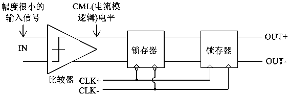
[0022] like Image 6 As shown, the high-speed latch that can receive millivolt-level signals includes a reference current source that provides a reference current for the latch; a sampling amplifier circuit that samples and amplifies the input signal; a latch circuit that converts the sampling point of the sampling amplifier circuit to The data is latched; the current amplifying circuit amplifies the charge and discharge current of the sampling circuit when the latch is switched from the latching state to the sampling state; the sampling amplifying circuit is connected to the current amplifying circuit, and the current amplifying circuit is connected to the latching circuit; The current amplification circuit includes an emitter follower. Th...


PUM


Abstract

The invention discloses a high-speed latch capable of receiving millivolt signals. The latch comprises a reference current source used for providing a reference current for the latch; a sampling amplification circuit for carrying out sampling amplification on input signals; a latch circuit for carrying out latch on sampling point data of the sampling amplification circuit; and a current amplification circuit for carrying out amplification on charging and discharging current of the sampling circuit when the latch is switched from a latch state to a sampling state. The sampling amplification circuit is connected with the current amplification circuit; and the current amplification circuit is connected with the latch circuit. The current amplification circuit comprises an emitter follower, wherein current gain of the emitter follower is beta; and when the latch is switched from the latch state to the sampling state, the charging and discharging current of the sampling circuit has enough current to charge / discharge an output node after being amplified for beta times by the current amplification circuit. The high-speed latch solves the problem of reception of the millivolt high-speed signals of the latch, reduces a comparator structure of a conventional EOM circuit, reduces power consumption and simplifies circuit structure.

Description

technical field [0001] The invention relates to a high-speed latch capable of receiving millivolt signals. Background technique [0002] Modern communication has higher and higher requirements on data rate and transmission distance, but the influence of non-ideal factors such as crosstalk and reflection makes the signal quality received by the receiver very poor. Therefore, in high-speed signal transmission circuits, more and more EOM (Eye Diagram Detection) circuits are integrated to detect the quality of the received signal, and the equalizer coefficients are adjusted by judging the opening degree of the eye diagram to restore the correct Data, the sampler is an important part of the EOM circuit. [0003] At present, the more common practice in EOM circuits is to first pass through a high-speed comparator to convert the small signal into a CML (current mode) level (generally 200mV~800mV), and then send it to the flip-flop for sampling, such as figure 1 shown. This schem...

Claims


Application Information

Patent Timeline
Patent Type & Authority Patents(China)
IPC IPC(8): H03K3/012H03K3/356
CPCH03K3/012H03K3/356
Inventor 张冰唐书林
Owner CHENGDU CORPRO TECH CO LTD
Why Eureka
Try Eureka