Remote pulse condition monitoring system

A monitoring system and pulse condition technology, applied in the field of pulse diagnostic instruments, can solve the problems of pulse diagnostic instruments without establishing a pulse condition database, limited judgment, monitoring human health, etc., to achieve remote monitoring of human health, eliminating signal interference, and good innovative ideas. Effect

Inactive Publication Date: 2016-03-16
JINAN UNIVERSITY
View PDF8 Cites 3 Cited by
  • Summary
  • Abstract
  • Description
  • Claims
  • Application Information

AI Technical Summary

Problems solved by technology

[0007] (1) At this stage, the mobile phone pulse diagnosis instrument can display the diagnosis results of the pulse diagnosis instrument, but this kind of product cannot share the diagnosis information to other users in the family in time, and cannot play the role of remote monitoring, and because the pulse condition is matched on the mobile phone , the processing accuracy of the pulse condition is lacking, the judgment of the pulse condition is limited to whether there is a pulse or not, and the diagnostic information is slightly less
[0008] (2) At present, pulse diagnosis instrument technology has been promoted to the mass market, such as "portable pulse condition instrument", but such products have failed to play the role of intelligent terminal technology and mobile communication technology, and cannot build a monitoring system using pulse diagnosis instrument monitor human health
[0009] (3) Existing pulse diagnosis instruments that can utilize communication network technology have not set up a pulse condition database, and cannot use electronic technology to process and distinguish pulse condition signals in real time, but transmit the collected data to hospitals for diagnosis by doctors. It makes the pulse diagnosis instrument's diagnosis to the user cumbersome and does not have real-time performance

Method used


Image

  • Remote pulse condition monitoring system
  • Remote pulse condition monitoring system

Examples


Embodiment

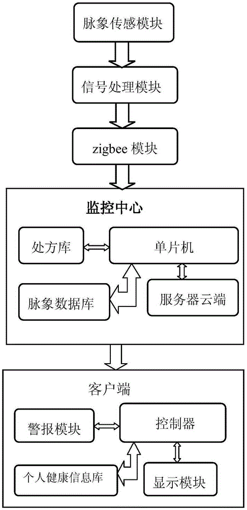
[0028] Such as figure 1 Shown, a kind of remote pulse monitoring system, pulse sensing module, signal processing module, ZigBee module, monitoring center and client, described monitoring center includes pulse database, prescription storehouse, server cloud and single-chip microcomputer, and described client includes control device, alarm module, display module and personal health database; the pulse sensor module, signal processing module and ZigBee module are combined into a functional module, which is called module A here; the monitoring center and the client are two other functions Modules, referred to as Module B and Module C, respectively. Described pulse condition sensing module transmits the collected signal to the signal processing module, and the signal processing module carries out hardware filtering and amplifying the received signal, and then the processed signal is sent to the monitoring center through the ZigBee module; the single-chip microcomputer in the monito...


PUM


Abstract

The invention discloses a remote pulse condition monitoring system, which comprises a pulse condition sensing module, a signal processing module, a ZigBee module, a monitoring center and a client, wherein the monitoring center comprises a pulse condition database, a prescription library, a server cloud and a single chip; the client comprises a controller, an alarm module, a display module and a personal health database; the pulse condition sensing module is used for transmitting collected signals to the signal processing module; the signal processing module is used for performing hardware filter and amplification on the received signals; the ZigBee module is used for transferring the signals, which is subjected to hardware processing, to the single chip; the single chip is used for analyzing and judging the transmitted pulse condition signals by virtue of the pulse condition database, calling corresponding treatment suggestions from the prescription library and transmitting diagnosis information to the client; the client is used for displaying the diagnosis information by virtue of the display module; and the personal health database is used for storing the diagnosis information. The remote pulse condition monitoring system disclosed by the invention is quite strong in practicability and broad in prospect of industrial application.

Description

technical field [0001] The invention relates to a pulse diagnosis instrument technology, in particular to a remote pulse condition monitoring system. Background technique [0002] In the past 10 years, a variety of pulse diagnosis instruments with different performances have been developed in China. The technology of using pulse diagnosis instruments to obtain human pulse information has been relatively mature. Combining pulse diagnosis instruments with intelligent terminals, computers, and mobile communications constitutes a The conception of the system becomes a breakthrough, and the relevant existing technologies are as follows: [0003] (1) Mobile phone pulse monitor (patent number CN201110461461), which is connected in sequence with a mobile phone, an interface circuit, and a pulse sensor. It can be operated by oneself, and the pulse sensor is placed on the wrist. The circuit is transmitted to the mobile phone, and the pulse information can be seen in real time from th...

Claims


Application Information

Patent Timeline
Patent Type & Authority Applications(China)
IPC IPC(8): A61B5/02G06F19/00
CPCA61B5/02A61B5/0004A61B5/0022A61B5/4854G06F19/3418G16H10/60
Inventor 黄伟英张培熙张凯鹏林韵立刘嘉俊范志广林金漩陈明燊孙立雷兆宜
Owner JINAN UNIVERSITY
Why Eureka
Try Eureka