Friction stir welding device and method by applying ultrasonic vibration from bottom
An ultrasonic vibration and friction stir technology, applied in welding equipment, non-electric welding equipment, metal processing equipment, etc., can solve the problems of different ways of applying ultrasonic vibration energy and different effects, so as to improve joint performance, enhance flow, reduce The effect of weak connection tendency
- Summary
- Abstract
- Description
- Claims
- Application Information
AI Technical Summary
Problems solved by technology
Method used
Image

Examples
specific Embodiment approach 1
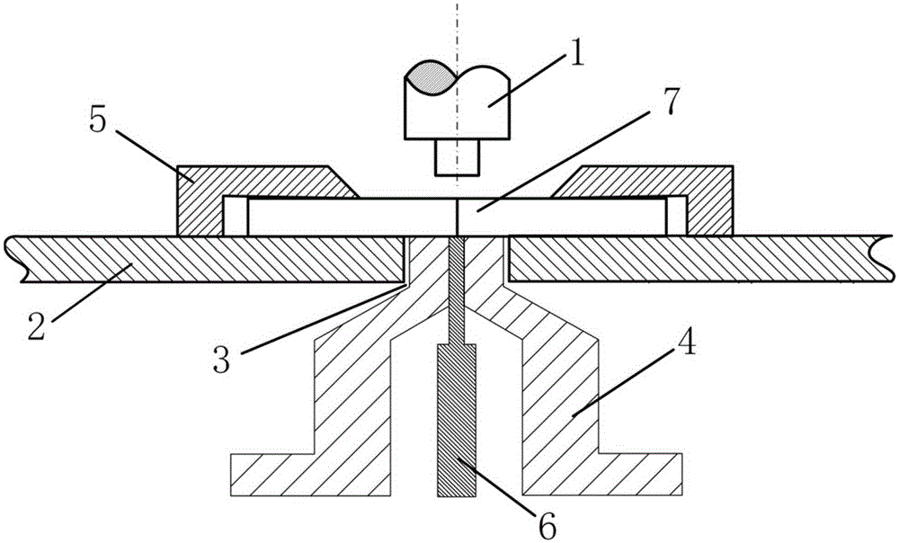
[0018] Specific implementation mode one: combine figure 1 Describe this embodiment, this embodiment comprises a stirring head 1, a workbench 2, a support base 4, a clamping tool 5 and an ultrasonic vibration device 6,
[0019] The worktable 2 processes a rectangular groove 3 along the welding direction; a support base 4 is arranged in the rectangular groove 3, and the upper end surface of the support base 4 is at the same height as the upper end surface of the workbench 2, and a circular through hole is processed in the center of the support base 4, During the welding process, the pressure from the axial direction is mainly borne by the support base 4; the ultrasonic vibration device 6 is fixed below the workbench 2 and coaxially arranged with the circular through hole in the center of the support base 4. During the welding process, the ultrasonic vibration device 6 will Ultrasonic vibration energy is vertically applied to the workpiece 7 around the stirring needle from the bo...
specific Embodiment approach 2
[0020] Specific implementation mode two: combination figure 1 Describe this embodiment, the welding method of this embodiment comprises the following steps:
[0021] Step 1. Fixing the support base:
[0022] Fix the support base 4 in the rectangular groove 3 of the workbench, the support base 4 is at the same height as the workbench 2, and keep a gap of 1-5 mm between the two sides of the support base 4 and the two sides of the rectangular groove 3 to prevent mutual friction during welding, support The through hole on the base 4 is located directly below the stirring head 1;
[0023] Step 2. Fixing of the ultrasonic vibration device:
[0024] Fix the ultrasonic vibration device 6 below the support base 4, the end of the ultrasonic vibration device 6 enters the central through hole of the support base 4, and the upper end surface of the ultrasonic vibration device 6 is on the same level as the upper end surface of the workbench 2, and the end Maintain a transition fit with t...
specific Embodiment approach 3
[0027] Specific implementation mode three: combination figure 1 To describe this embodiment, the power supply of the ultrasonic vibration device 6 in Step 3 of this embodiment is 2000W. With such arrangement, more ultrasonic vibration energy can be applied to the weld seam from the bottom within the range that the workpiece 7 to be welded can bear. Other compositions and connections are the same as those in the second embodiment.
PUM
| Property | Measurement | Unit |
|---|---|---|
| Power supply | aaaaa | aaaaa |
Abstract
Description
Claims
Application Information
 - Generate Ideas
- Intellectual Property
- Life Sciences
- Materials
- Tech Scout
- Unparalleled Data Quality
- Higher Quality Content
- 60% Fewer Hallucinations
Browse by: Latest US Patents, China's latest patents, Technical Efficacy Thesaurus, Application Domain, Technology Topic, Popular Technical Reports.
© 2025 PatSnap. All rights reserved.Legal|Privacy policy|Modern Slavery Act Transparency Statement|Sitemap|About US| Contact US: help@patsnap.com