A film sticking machine

A film laminating machine and frame technology, which is applied in the direction of layered products, lamination devices, lamination, etc., can solve the problems of not being able to guarantee the film at all times, difficult to operate, and tightly pressed on the surface of stainless steel or aluminum profiles, etc.

Active Publication Date: 2016-03-16
广东原创力量新媒体产业有限公司
View PDF2 Cites 6 Cited by
  • Summary
  • Abstract
  • Description
  • Claims
  • Application Information

AI Technical Summary

Problems solved by technology

[0002] At present, the existing film laminating machine is composed of a frame, a film fixed transmission device, a stainless steel or aluminum profile transmission device, a film pressing wheel device and a film cutter device. The film fixed transmission device sends the film to be pasted to the stainless steel or aluminum profile transmission device. On the surface of the device, the film clings to the surface of the stainless steel or aluminum profile under the action of the film pressing wheel device and moves under the push of the stainless steel or aluminum profile conveying device to complete a whole strip of stainless steel or aluminum profile surface film, and then the film cutter The device cuts the film and completes the film application; however, the stainless steel or aluminum profile conveying device of the existing film lamination machine is fixed, and when it is necessary to apply films with different angles on the surface of the stainless steel or aluminum profile, it is necessary to adjust the guiding device of the film material. Therefore, it is easy to cause the disadvantages of crooked film sticking and wrinkling, and it is not easy to operate; and the film pressing wheel device of the existing film laminating machine also has the problem that it cannot always ensure that the film is pressed tightly on the surface of the stainless steel or aluminum profile

Method used


Image

  • A film sticking machine
  • A film sticking machine
  • A film sticking machine

Examples


Embodiment Construction

[0017] In the following, the present invention will be further described in conjunction with the accompanying drawings and specific embodiments, so as to understand more clearly the technical idea claimed in the present invention.

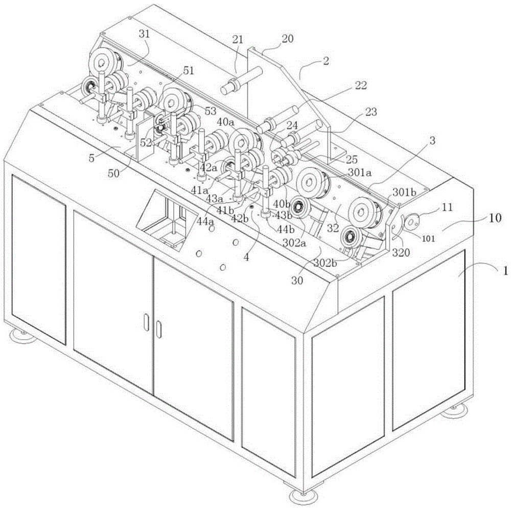
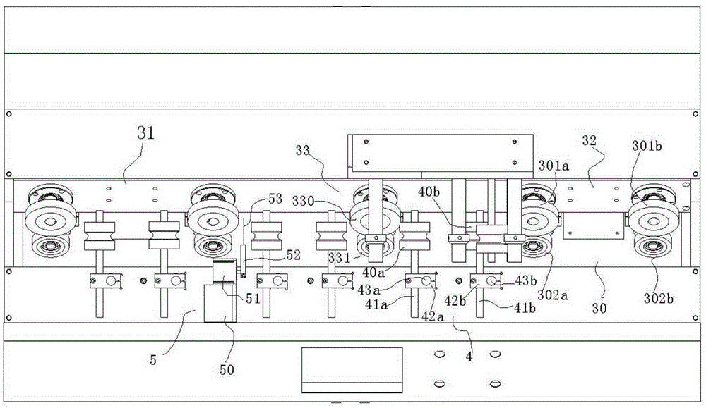
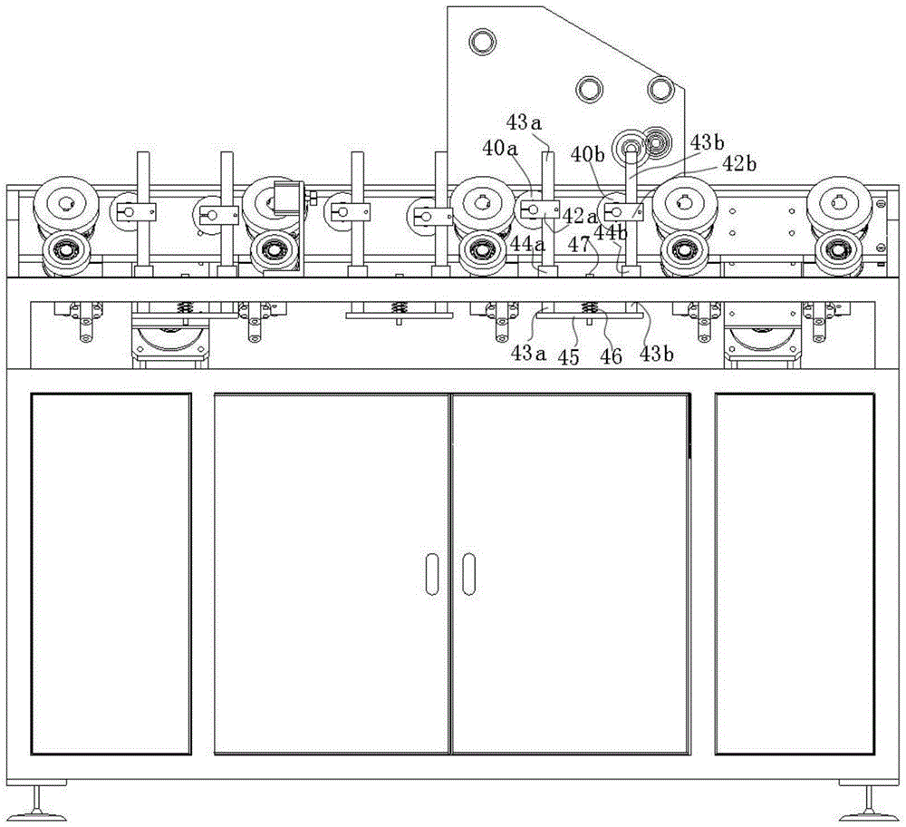
[0018] Such as Figure 1-5 A film laminating machine of the present invention is shown, comprising a frame 1, a film fixing conveying device 2, a stainless steel or aluminum profile conveying device 3, a film pressing wheel device 4 and a film cutter device 5, and the film fixing conveying device 2 includes a fixed plate 20, a first wheel 21 for installing a fixed film coil, a second wheel 22 for straightening and conveying a film, a third wheel 23, a fourth wheel 24 and a fifth wheel 25, the The fixed plate 20 is installed and fixed on the frame 1, the first runner 21 is installed and fixed on the upper left corner of the fixed plate 20, the second runner 22 and the third runner 23 are installed and fixed on the fixed plate 20 at the same height a...


PUM


Abstract

A film sticking machine is disclosed. The film sticking machine comprises a rack, a film fixing and conveying device, a stainless steel or aluminum section conveying device, film pressing wheel devices and a film cutter device. The film fixing and conveying device comprises a fixing plate, a first runner for mounting and fixing a film coil, a second runner, a third runner, a fourth runner and a fifth runner, with the second to fifth runners being used for straightening and conveying film. The stainless steel or aluminum section conveying device comprises a section feeding wheel device, a section discharging wheel deice and a feeding wheel device fixing plate. Each of the film pressing wheel devices comprises a first pressing wheel, a second pressing wheel, a first pressing wheel shaft, a second pressing wheel shaft, a first shaft connecting block, a second shaft connecting block, a first fixing bar, a second fixing bar, a first bar sleeve, a second bar sleeve, a connecting plate, a spring and a spring loop bar. The angle of the feeding wheel device fixing plate can be adjusted. The film sticking machine is advantageous in that the angle of the section conveying device can be adjusted, and the film pressing wheel devices ensure that film is tightly pressed on the surface of a section all the time.

Description

technical field [0001] The invention relates to the technical field of film laminating machines, in particular to a film laminating machine for laminating a protective film on the surface of stainless steel or aluminum profiles. Background technique [0002] At present, the existing film laminating machine is composed of a frame, a film fixed transmission device, a stainless steel or aluminum profile transmission device, a film pressing wheel device and a film cutter device. The film fixed transmission device sends the film to be pasted to the stainless steel or aluminum profile transmission device. On the surface of the device, the film clings to the surface of the stainless steel or aluminum profile under the action of the film pressing wheel device and moves under the push of the stainless steel or aluminum profile conveying device to complete a whole strip of stainless steel or aluminum profile surface film, and then the film cutter The device cuts the film and completes...

Claims


Application Information

Patent Timeline
Patent Type & Authority Applications(China)
IPC IPC(8): B32B37/00B32B37/10
CPCB32B37/0046B32B37/10
Inventor 谢新勇
Owner 广东原创力量新媒体产业有限公司
Why Eureka
Try Eureka