Rear view mirror for narrowing blind zone behind vehicle

A blind spot and rear view technology, applied in vehicle parts, optical observation devices, transportation and packaging, etc., can solve the problems of affecting the speed of the vehicle, the difficulty of left and right rear view mirrors, and the easy occurrence of accidents, so as to increase safety and reduce The effect of blind spot and safety accident avoidance

Inactive Publication Date: 2016-03-16
余嘉伟
View PDF0 Cites 1 Cited by
  • Summary
  • Abstract
  • Description
  • Claims
  • Application Information

AI Technical Summary

Problems solved by technology

Since the left and right rearview mirrors are located on the door and protrude out of the car body, the vehicle has a certain resistance during driving, which affects the speed of the vehicle.
In addition, the exterior rearview mirror cannot illuminate the direct rear of the vehicle. When the object behind the vehicle is lower than the vehicle body, the interior rearview mirror of the vehicle cannot illuminate it, which is prone to accidents.
[0003] It is difficult for most drivers to pay attention to the situation in front of the vehicle and the situation of the left and right rearview mirrors at the same time, especially for new drivers, it is easy to ignore the situation of the other side because they pay attention to the situation on one side , leading to an accident

Method used


Image

  • Rear view mirror for narrowing blind zone behind vehicle

Examples


Embodiment Construction

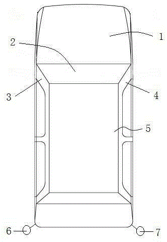
[0013] Such as figure 1 As shown, a rearview lens for reducing blind spots behind a car is characterized in that it includes a car body 1, a windshield 2, a left pillar of the windshield 3, a right pillar of the windshield 4, a roof cover 5, and a left camera 6 , right camera 7, left display screen 8 and right display screen 9; the left rearview mirror of the car body 1 is replaced by the left camera 6, and the right rearview mirror is replaced by the right camera 7; the left camera 6 is arranged side by side Next to the left rear headlight of the car; the right camera 7 is arranged side by side next to the right rear headlight of the car; the left display screen 8 and the right display screen 9 are arranged side by side above the instrument panel in the vehicle body.

[0014] The position of the left camera 6 and the position of the right camera 7 are on the same horizontal line.

[0015] The position of the left display screen 8 and the position of the right display screen ...


PUM


Abstract

The invention provides a rear view mirror for narrowing a blind zone behind a vehicle. The rear view mirror comprises a vehicle body, a front windshield, a front windshield left column, a front windshield right column, a vehicle roof cover, a left camcorder lens, a right camcorder lens, a left display screen and a right display screen, wherein a left rear view mirror of the vehicle body is replaced with the left camcorder lens; a right rear view mirror is replaced with the right camcorder lens; the left camcorder lens is arranged next to a left rear head lamp of the vehicle side by side; the right camcorder lens is arranged next to a right rear headlamp of the vehicle side by side; the left display screen and the right display screen are arranged above an instrument panel in the vehicle body side by side. According to the rear view mirror disclosed by the invention, not only can the air resistance of the vehicle when the vehicles runs be reduced, but also the display screens are arranged above the instrument panel in the vehicle, so that a driver can observe the travel situation at the left rearward and the travel situation at the right rearward when observing the travel situation in front of the vehicle, so that safety accidents caused by that the driver observes the travel situation in front of the vehicle but neglects the travel situation behind the vehicle are avoided, and the driver can conveniently and safely drive the vehicle.

Description

technical field [0001] The invention relates to the field of automobiles, in particular to a rearview lens for reducing blind spots behind a vehicle. Background technique [0002] The rearview mirror is a tool for the driver to directly obtain external information such as the rear, side and bottom of the car while sitting in the cab seat. Divided according to the type of installation, rearview mirrors can be divided into interior rearview mirrors and exterior rearview mirrors. The interior rearview mirror is a mirror that can confirm the rear scene without greatly changing the forward line of sight during driving; left and right rearview mirrors The mirror is generally installed on the door. Since the left and right rearview mirrors are located on the door and protrude out of the vehicle body, the vehicle has certain resistance during driving, which affects the speed of the vehicle. In addition, the exterior rearview mirror cannot illuminate the situation directly behind t...

Claims


Application Information

Patent Timeline
Patent Type & Authority Applications(China)
IPC IPC(8): B60R1/00
CPCB60R1/00B60R2300/101B60R2300/105B60R2300/802B60R2300/8046
Inventor 余嘉伟
Owner 余嘉伟
Why Eureka
Try Eureka