Pressure electricity generating device realizing electricity generation through driving impellers by fluid working medium

A technology of fluid working medium and pressure power generation, which is applied in the direction of hydroelectric power generation, mechanical power generation mechanism, engine components, etc. It can solve the problems of low cost performance of equipment, large mechanical force, expensive piezoelectric materials, etc., and achieve convenient maintenance and maintenance. The effect of a small number of parts and a simple structure

Inactive Publication Date: 2016-03-16
NANJING UNIV OF AERONAUTICS & ASTRONAUTICS
View PDF6 Cites 1 Cited by
  • Summary
  • Abstract
  • Description
  • Claims
  • Application Information

AI Technical Summary

Problems solved by technology

[0005] 1. The principle is mostly to use magnetic power generation and piezoelectric material to generate power, and the energy conversion efficiency is low, and the piezoelectric material is relatively expensive, which reduces the cost performance of the equipment
[0006] 2. The structural design of the device is weak and cannot withstand large mechanical forces
[0007] 3. The objects of collected energy have great limitations. There are strict requirements on the speed and size of power objects. Most of them can only collect the potential energy of pedestrians walking. The generated electric energy is relatively small and the application range is narrow

Method used


Image

  • Pressure electricity generating device realizing electricity generation through driving impellers by fluid working medium
  • Pressure electricity generating device realizing electricity generation through driving impellers by fluid working medium
  • Pressure electricity generating device realizing electricity generation through driving impellers by fluid working medium

Examples


Embodiment Construction

[0040] Below in conjunction with accompanying drawing, technical scheme of the present invention is described in further detail:

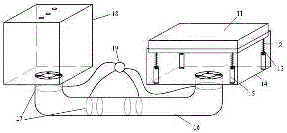
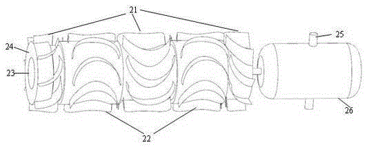
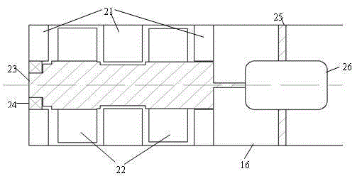
[0041] Such as figure 1 As shown, the present invention discloses a pressure power generation device based on a fluid working medium driving an impeller to generate electricity, including a pressure module, a circulation pipeline, a storage bin, an energy storage capacitor, and several impeller power generation units arranged in the circulation pipeline;

[0042] The circulation pipeline is used to connect the pressure module and the storage bin;

[0043] The pressure module is used to press the fluid working medium in it to the storage bin through the circulation pipeline when it is pressed by an external force, and to suck the fluid working medium back from the storage bin when the external force is removed;

[0044] The energy storage capacitor is connected to each impeller power generation unit, and is used to store the electric energy generat...


PUM


Abstract

The invention discloses a pressure electricity generating device realizing electricity generation through driving impellers by fluid working medium. The pressure electricity generating device comprises a pressure module, a circulation pipeline, a storage bin, an energy storage capacitor, and a plurality of impeller electricity generating units arranged in the circulation pipeline, wherein the circulation pipeline is used for connecting the pressure module and the storage bin; the pressure module is used for pressing the fluid working medium therein to flow to the storage bin through the circulation pipeline under the compression of external force, and sucking back the fluid working medium from the storage bin when the external force is removed; the energy storage capacitor is connected with the impeller electricity generating units; and each impeller electricity generating unit comprises a motor, a rotor shaft, a plurality of stator blade sets and a plurality of rotor blade sets, wherein rotary force produced through water flow is exerted onto the rotor blade sets behind the stator blade sets through the stator blade sets, and further the rotor shaft is driven to rotate to enable an engine to generate electricity. The pressure electricity generating device provided by the invention is low in cost, can bear tremendous pressure, is adjustable in size, and has a wide application scope.

Description

technical field [0001] The invention relates to the field of pressure power generation, in particular to a pressure power generation device based on a fluid working medium driving an impeller to generate power. Background technique [0002] Pressure power generation is a power generation method that generates electric energy through pressure. It can collect the energy generated by different objects such as pedestrians, vehicles, and trains when they pass through pressure power generation equipment, and convert it into electric energy for use. It is a green and clean power generation method. [0003] At present, various countries including Japan and the United States have developed several different types of pressure power generation devices, which can be divided into: pressure power generation equipment designed to generate power by cutting magnetic induction lines with permanent magnets, and the principle of power generation based on piezoelectric materials under pressure T...

Claims


Application Information

Patent Timeline
Patent Type & Authority Applications(China)
IPC IPC(8): F03G7/00F03B13/00F03B3/12F03B3/18
CPCF03B3/121F03B3/18F03B13/00F03G7/00Y02E10/20
Inventor 吴明峰袁艺青
Owner NANJING UNIV OF AERONAUTICS & ASTRONAUTICS
Why Eureka
Try Eureka