Pressing-injecting oil cylinder with pressurization system

A technology of supercharging system and oil cylinder, which is applied in the field of oil cylinder and injection cylinder, can solve the problems of complex structure, increased cost and reduced injection speed, and achieves the effect of simple structure, convenient installation and low cost.

Inactive Publication Date: 2016-03-16
SUZHOU SANJI FOUNDRY EQUIP
View PDF4 Cites 3 Cited by
  • Summary
  • Abstract
  • Description
  • Claims
  • Application Information

AI Technical Summary

Problems solved by technology

Now the general methods to achieve the above requirements are: 1. Increase the injection cylinder to increase the injection force, but the injection speed will decrease under the same situation, so to achieve the same speed at this time, it is necessary to increase the displacement of the oil pump. 2. To increase the pressure instantaneously without enlarging the cylinder, it is necessary to reconfigure a booster system, which complicates the structure and increases the cost

Method used


Image

  • Pressing-injecting oil cylinder with pressurization system

Examples


Embodiment Construction

[0013] The technical scheme of the present invention will be further explained below in conjunction with the drawings:

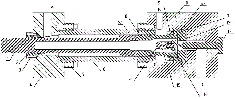
[0014] Such as figure 1 As shown, the injection cylinder with its own booster system includes the injection piston rod 1, the cylinder barrel 6, the spring gland 7, the booster piston rod 8, the booster piston 11, the one-way valve sleeve 12, and the valve core top Rod 13, one-way valve spring 14 and one-way valve core 15, the front end of the cylinder barrel 6 is mounted with a cylinder front cover 4, the rear end is mounted with a cylinder rear cover 10, the injection piston rod 1 passes through the cylinder front cover 4 and is placed The cylinder barrel 6 of the oil cylinder can move in the axial direction. The booster piston 11 is located in the inner cavity of the back cover 10 of the cylinder. The booster piston 11 is connected and fixed with one end of the booster piston rod 8 through the booster piston rod cover 9 The other end of the pressure piston r...


PUM


Abstract

The invention relates to a pressing-injecting oil cylinder with a pressurization system. The pressing-injecting oil cylinder is characterized in that a pressing-injecting piston rod passes through a front cover of the oil cylinder and then is positioned into a barrel of the oil cylinder; a pressurizing position is positioned in an inner cavity of a rear cover of the oil cylinder; one end of a pressurizing piston rod is connected to the pressurizing piston while the other end of the pressurizing piston rod is positioned into the barrel of the oil cylinder; a one-way valve sleeve is mounted into an axial through hole of the pressurizing piston; a through hole is formed in the axis position of the pressurizing piston rod; a blind hole is formed in the axis position of the pressing-injecting piston rod; a one-way valve element is mounted on a spring pressing cover in the through hole through an one-way valve spring; a first oil port in the front cover of the oil cylinder communicates with a rod port of the pressing-injecting piston rod; a second oil port in the rear cover of the oil cylinder and an oil channel communicate with the rod port of the pressurizing piston rod; a third port in the rear cover of the oil cylinder and the oil channel correspondingly communicate with the through hole in the pressurizing piston rod and the blind hole in the pressing-injecting piston rod through inner holes of the one-way valve sleeve; a valve element ejector rod is inserted from the rear cover of the oil cylinder into the inner holes of the one-way valve sleeve and is opposite to the one-way valve element. According to the pressing-injecting oil cylinder, the one-way valve element can be automatically opened and closed to achieve piston area difference, and thus the pressurization effect can be achieved.

Description

Technical field [0001] The invention relates to an oil cylinder, in particular to an injection oil cylinder with a booster system, belonging to the technical field of hydraulic systems. Background technique [0002] Because the general die-casting process requires a period of high-speed filling during the filling process, and the injection force is required to be increased instantaneously at the end of the injection, so as to ensure complete filling and ensure product pass rate. Now the general methods to achieve the above requirements are: 1. Increase the injection cylinder to increase the injection force, but the injection speed will decrease under the same conditions, so to achieve the same speed at this time is to increase the oil pump displacement. 2. It is necessary to reconfigure a set of pressure boosting system to instantaneously pressurize without increasing the oil cylinder, so the structure is complicated and the cost is increased. Summary of the invention [0003] Th...

Claims


Application Information

Patent Timeline
Patent Type & Authority Applications(China)
IPC IPC(8): F15B15/17F15B3/00
Inventor 孔跃明熊守美万水平赵峰
Owner SUZHOU SANJI FOUNDRY EQUIP
Why Eureka
Try Eureka