Energy-saving deicing dynamic ice-making system and deicing operation method thereof

An operation method and dynamic technology, applied in the field of air conditioners, can solve the problems of ice blockage at the outlet end, inconvenient operation, affecting the effect of ice making and circulation, etc., and achieve the effect of solving ice blockage.

Active Publication Date: 2016-03-16
SHENZHEN DAS INTELLITECH CO LTD
View PDF5 Cites 6 Cited by
  • Summary
  • Abstract
  • Description
  • Claims
  • Application Information

AI Technical Summary

Problems solved by technology

[0002] After the dynamic ice maker makes ice for a period of time, sometimes due to the temperature control of the dynamic ice maker or the fluctuation of the cooling supply of the ice maker, the ice water mixture (that is, dynamic ice) will be overcooled in the dynamic ice maker. There will be ice blockage at the outlet end of the pulp) outflow, which will affect the ice making effect and circulation
At present, the methods used to solve the problem of ice blockage include: 1. The method of melting ice crystals by heating with electric heating wire, but the heating temperature of electric heating wire is difficult to control. If the temperature is too high, the efficiency and effect of ice making will be affected; 2. By adopting the method of high temperature water circulation To remove the accumulated ice crystals, this method needs to stop the dynamic ice machine, which is inconvenient to operate, and also affects the use of the ice machine and the normal operation of the entire system

Method used


Image

  • Energy-saving deicing dynamic ice-making system and deicing operation method thereof

Examples


Embodiment Construction

[0022] In order to have a clearer understanding of the technical features, purposes and effects of the present invention, the specific implementation manners of the present invention will now be described in detail with reference to the accompanying drawings.

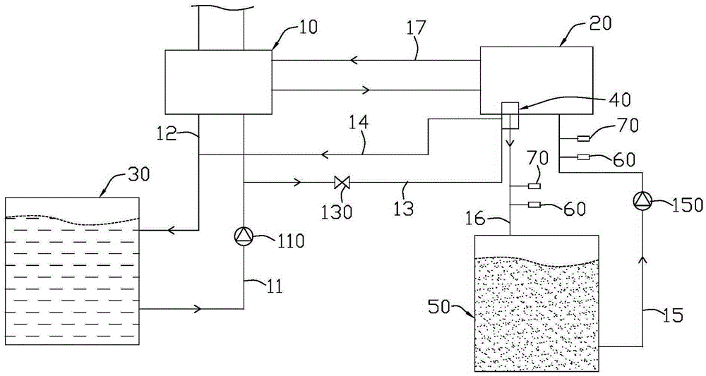
[0023] Such as figure 1 As shown, an energy-saving and deicing dynamic ice-making system according to an embodiment of the present invention includes an ice-making host 10, a dynamic ice machine 20, a cooling tower 30, a first water inlet pipe 11 and a first water outlet pipe 12, and a de-icing mechanism 40 , and the second water inlet pipe 13 and the second water outlet pipe 14. The cooling tower 30 is connected to the main ice maker 10 through the first water inlet pipe 11 and the first water outlet pipe 12 to form a cooling circuit; the deicing mechanism 40 is arranged at the outlet end of the dynamic ice maker 20, and the water for the cooling tower 30 is inside Circulation; the second water inlet pipe 13 is connec...


PUM


Abstract

The invention discloses an energy-saving deicing dynamic ice-making system and a deicing operation method thereof. The energy-saving deicing dynamic ice-making system comprises an ice-making main machine, a dynamic ice-making machine, a cooling tower, a first water inlet pipe and a first water outlet pipe. The cooling tower is connected with the ice-making main machine through the first water inlet pipe and the first water outlet pipe to form a cooling loop. The dynamic ice-making system further comprises a deicing mechanism arranged at the outlet end of the dynamic ice-making machine, a second water inlet pipe and a second water outlet pipe. The second water inlet pipe is connected between the water inlet end of the deicing mechanism and the first water inlet pipe, the second water outlet pipe is connected between the water outlet end of the deicing mechanism and the first water outlet pipe, and therefore a deicing energy supply loop is formed by connecting the cooling tower and the deicing mechanism. High-temperature water of the cooling tower is drained to the deicing mechanism at the outlet end of the dynamic ice-making machine, water of the cooling tower is used for cold and heat exchange at the outlet end of the dynamic ice-making machine so as to solve the problem of ice blockage at the outlet end, and energy saving and environment friendliness are achieved.

Description

technical field [0001] The invention relates to the technical field of air conditioning, in particular to an energy-saving and deicing dynamic ice making system and a deicing operation method thereof. Background technique [0002] After the dynamic ice maker makes ice for a period of time, sometimes due to the temperature control of the dynamic ice maker or the fluctuation of the cooling supply of the ice maker, the ice water mixture (that is, dynamic ice) will be overcooled in the dynamic ice maker. There will be ice blockage at the outlet end of the slurry), which will affect the ice making effect and circulation. At present, the methods used to solve the problem of ice blockage include: 1. The method of melting ice crystals by heating with electric heating wire, but the heating temperature of electric heating wire is difficult to control. If the temperature is too high, the efficiency and effect of ice making will be affected; 2. By adopting the method of high temperature...

Claims


Application Information

Patent Timeline
Patent Type & Authority Applications(China)
IPC IPC(8): F25C1/00
CPCF25C1/00F25C2500/08
Inventor 蒋辉华梁国挥谢辉优
Owner SHENZHEN DAS INTELLITECH CO LTD
Why Eureka
Try Eureka