
A measuring device and measuring method for dusty gas flow velocity

A technology of gas flow rate and measuring device, which is applied in the direction of measuring fluid velocity by using pressure difference, etc., which can solve the problems of increasing the complexity of operation, unrepresentative measurement position, and clogging of measuring devices, etc., and achieves easy construction and sealing cover, and reduces Influence and improve the effect of measurement accuracy

Active Publication Date: 2018-08-17
STATE GRID FUJIAN ELECTRIC POWER CO LTD +3
View PDF11 Cites 1 Cited by
  • Summary
  • Abstract
  • Description
  • Claims
  • Application Information

AI Technical Summary

Problems solved by technology

[0002] The measurement of the flow rate of dusty gas has always had the problem of clogging the measuring device, especially in the case of vertical air flow. At present, there will be some problems in the application of commonly used measuring devices, such as flute tube, Venturi, back tube, etc. may cause blockage , a single Venturi tube or back tube will also affect the use because of the poor representativeness of the measurement position, and the ash discharge function can be set for the wing-shaped measurement device, but this not only increases the complexity of the operation, but may still affect the measurement or cause jam

Method used


Image

  • A measuring device and measuring method for dusty gas flow velocity
  • A measuring device and measuring method for dusty gas flow velocity
  • A measuring device and measuring method for dusty gas flow velocity

Examples


Embodiment Construction

[0021] The present invention will be further described below in conjunction with the accompanying drawings and specific embodiments.

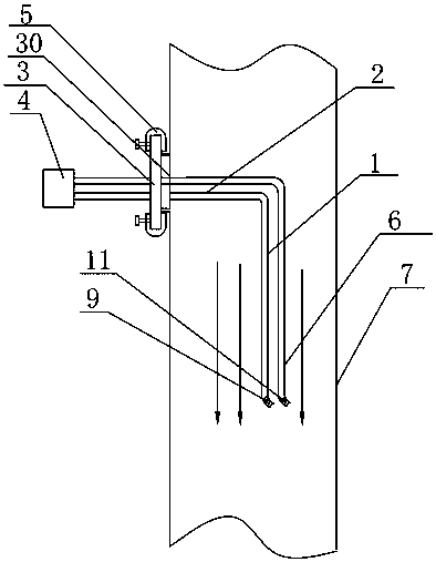
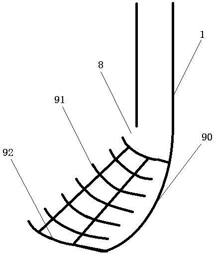
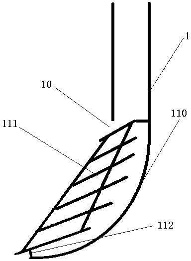
[0022] Such as Figure 1~3 As shown, the embodiment of the present invention provides a measuring device for the flow rate of dust-laden gas, which includes more than one positive pressure measuring tube 1 and a negative pressure measuring tube extending into the measured pipeline and parallel to the air flow in the measured pipeline 6. The bottom ends of the positive pressure sensing tube 1 and the negative pressure sensing tube 6 are provided with a positive pressure sensing port 8 and a negative pressure sensing port 10 respectively, and a positive pressure sensing port 8 is provided at the positive pressure sensing port 8. A diversion mechanism 9; a negative pressure diversion mechanism 11 is provided at the negative pressure take-off port 10; the positive pressure take-off pipe 1 and the negative pressure take-off pipe 6 stretch out to the...


PUM


Abstract

The invention relates to a measurement device of flow rate of dusty gas and a measurement method thereof. The measurement device comprises more than one positive pressure taking pipe and a negative pressure taking pipe. The positive pressure taking pipes stretch into a to-be-measured pipeline and are parallel to air flows in the to-be-measured pipeline. Positive pressure taking openings and a negative pressure taking opening are respectively arranged in the positive pressure taking pipes and the negative pressure taking pipe. A positive pressure flow guiding mechanism is arranged at each of the positive pressure taking openings. A negative pressure flow guiding mechanism is arranged at the negative pressure taking opening. The positive pressure taking pipes and the negative pressure taking pipe stretch out of the to-be-measured pipeline and then are connected with a differential pressure gauge via a lead-out pipe which is perpendicular to the positive pressure taking pipes and the negative pressure taking pipe. The positive pressure taking pipes are communicated with the positive pressure end of the differential pressure gauge. The negative pressure taking pipe is communicated with the negative pressure end of the differential pressure gauge. The lead-out pipe and the to-be-measured pipeline are sealed by a sealing cover. The outer side face of the sealing cover is fixed at the opening of the to-be-measured pipeline via multiple fixing buckles. The beneficial effects are that the measurement device is simple in structure, convenient to operate and capable of preventing blocking phenomena caused by dusty gas during the measurement; effects on measurement results are reduced; and measurement precision is improved.

Description

technical field [0001] The invention relates to the field of gas flow velocity measurement, in particular to a measuring device and a measurement method for dust-laden gas flow velocity. Background technique [0002] The measurement of the flow rate of dusty gas has always had the problem of clogging the measuring device, especially in the case of vertical air flow. At present, there will be some problems in the application of commonly used measuring devices, such as flute tube, Venturi, back tube, etc. may cause blockage , a single Venturi tube or back tube will also affect the use because of the poor representativeness of the measurement position, and the ash discharge function can be set for the wing-shaped measurement device, but this not only increases the complexity of the operation, but may still affect the measurement or cause clogged. Contents of the invention [0003] The object of the present invention is to provide a measuring device and method for the flow ra...

Claims


Application Information

Patent Timeline
Patent Type & Authority Patents(China)
IPC IPC(8): G01P5/14
CPCG01P5/14
Inventor 陈宇陈献春陈稻香陈涛曾忠旺林阿平王寅张民赦薛建成林林星
Owner STATE GRID FUJIAN ELECTRIC POWER CO LTD
Learn More