Damping-optimization design method of panoramic observation mirror equipment structure

An optimized design and observation mirror technology, applied in computing, special data processing applications, instruments, etc., can solve problems such as backward detection range and accuracy, unclear optimization design direction, long new product development cycle, etc., to reduce blindness, The effect of shortening the development period and reducing the assessment cost

Active Publication Date: 2016-03-16
河南平原光电有限公司
View PDF2 Cites 6 Cited by
  • Summary
  • Abstract
  • Description
  • Claims
  • Application Information

AI Technical Summary

Problems solved by technology

The optimization design direction is not clear, resulting in a long new product development cycle
At the same time, due to the lack of application of advanced anti-vibration analysis technology, although the anti-vibration performa...

Method used


Image

  • Damping-optimization design method of panoramic observation mirror equipment structure
  • Damping-optimization design method of panoramic observation mirror equipment structure
  • Damping-optimization design method of panoramic observation mirror equipment structure

Examples


Embodiment 1

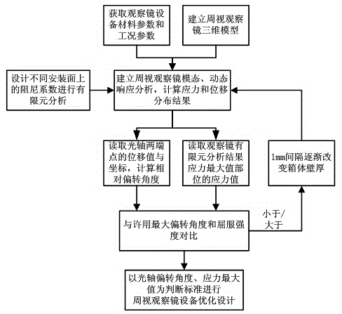
[0025] Such as figure 1 as shown,

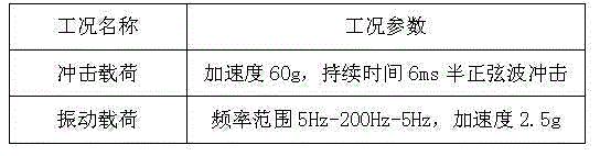
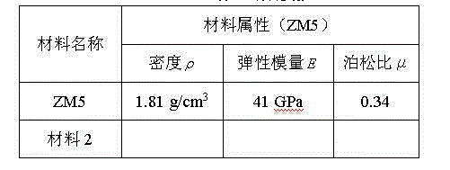
[0026] Step 1. Obtain the material parameters and working condition parameters of the observation mirror equipment. The parameters required for finite element simulation analysis are as follows in Table 1 and Table 2; including: ①Material parameters: density ,Elastic Modulus , Poisson's ratio μ; ② Operating parameters: impact load acceleration, period, vibration frequency range, acceleration. ③The maximum allowable relative offset angle between the two ends of the optical axis of the observation mirror is 0.01°

[0027] Table 1 Material parameters

[0028]

[0029] Table 2 Working condition parameters

[0030]

[0031] Step 2. Use the 3D modeling software to establish a 3D model of the periscope observation mirror, and import the 3D model into the finite element simulation analysis software to generate a corresponding geometric model.

[0032] Step 3. Establish a finite element simulation analysis model, and select the two ends ...


PUM


Abstract

The invention discloses a damping-optimization design method of a panoramic observation mirror equipment structure. The method comprises the following steps: 1) obtaining material parameters and working condition parameters of observation mirror equipment, and analyzing and calculating the maximum relative deviation angle allowed by two end points of an optical axis of an observation mirror; 2) establishing a panoramic observation mirror three-dimensional model by using three-dimensional modeling software, and guiding finite element emulation analysis software to generate a geometric model; 3) establishing an finite element emulation analysis model; 4) reading the stress value and coordinate of a stress maximum value part and the displacement values and coordinates of the two end points of the optical axis of the observation mirror; 5) in allusion to the infinite element analysis model, setting different damping coefficients on boundary conditions of an equipment mounting surface, and repeating the step 4; and 6) repeating the steps 3-5, and when the deviation angle of the optical axis does not exceed an allowable value, taking the damping coefficient when the stress maximum value is nearest to the material yield strength and a body structure model of the observation mirror equipment as the optimum damping design schemes of the panoramic observation mirror equipment.

Description

technical field [0001] The invention belongs to the technical field of vehicle-mounted detector equipment design, and in particular relates to a structural vibration reduction optimization design method for peripheral viewing mirror equipment under extreme working conditions. Background technique [0002] Vehicle-mounted detectors such as peripheral observation mirror equipment have harsh detection conditions, complex vibration conditions, and many impacts. Their detection accuracy and structural reliability are greatly affected by working conditions. Aiming at the vibration and impact problems mainly faced by peripheral observation mirror equipment, the traditional method mainly adopts the rigidity of the structure to ensure the rigidity of the structure, the installation of shock absorbers to reduce the damage of vibration and impact to the equipment, and the use of viscoelastic damping and vibration reduction materials. Vibration reduction and other methods are used to el...

Claims


Application Information

Patent Timeline
IPC IPC(8): G06F17/50
Inventor 李金映陈菊意魏前岗王维博江楠王广奇刘金涛熊冀夏树策张金涛张永安李会玲
Owner 河南平原光电有限公司
Why Eureka
Try Eureka