
Load balancing method of radio local network

A wireless local area network and load balancing technology, applied in the direction of data exchange through path configuration, which can solve the problems of terminal service interruption, unsuccessful handover, and heavy load of the basic service group, avoiding service interruption, avoiding performance degradation, The effect of reducing blindness

Inactive Publication Date: 2007-02-14
ZTE CORP
View PDF0 Cites 25 Cited by
  • Summary
  • Abstract
  • Description
  • Claims
  • Application Information

AI Technical Summary

Problems solved by technology

As the environment in the WLAN changes and the number of terminals increases, wireless access points with strong signals will attract more mobile terminals to switch, causing sudden changes and imbalances in the load in the extended service group, reducing network stability and expanding The wireless network resources in the service group cannot be fully utilized
[0006] 2. The current wireless LAN switching mechanism will reduce the tolerance of the network and cause congestion easily
Since the handover of a mobile terminal only depends on the signal strength, if a terminal switches to a wireless access point with a saturated load according to the signal strength, the wireless access point will be congested, and all terminals served by the wireless access point will be congested. Service interruptions reduce network tolerance
[0007] 3. The handover success rate of mobile terminals is low, and the risk of handover is high
On the one hand, when a wireless access point with stronger signal strength is scanned and decided to switch, the terminal does not know whether the switch is successful, nor does it know whether the target wireless access point can provide the resources and service quality required by the terminal. Risk of unsuccessful, switching results are not guaranteed
On the other hand, as other terminals switch access, the load of the basic service group where the terminal is located is increased, and the terminal cannot avoid the load peak of the current basic service group. Once the load of the wireless access point is saturated, the service of the terminal danger of interruption

Method used


Image

  • Load balancing method of radio local network
  • Load balancing method of radio local network

Examples


Embodiment Construction

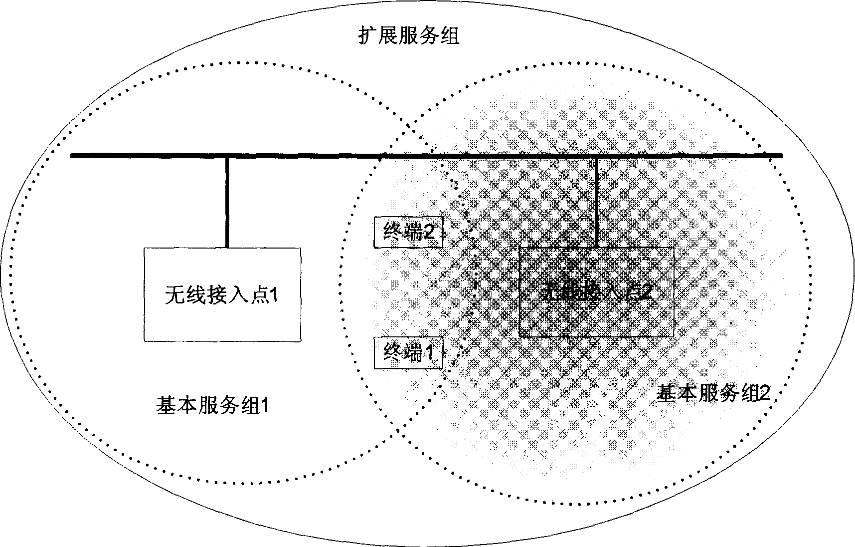
[0022] The wireless local area network environment described in the present invention includes at least two wireless access points and two terminals. Two wireless access points form an extended service group to provide access services for two terminals. The present invention will be described in further detail below in conjunction with the accompanying drawings and specific examples.

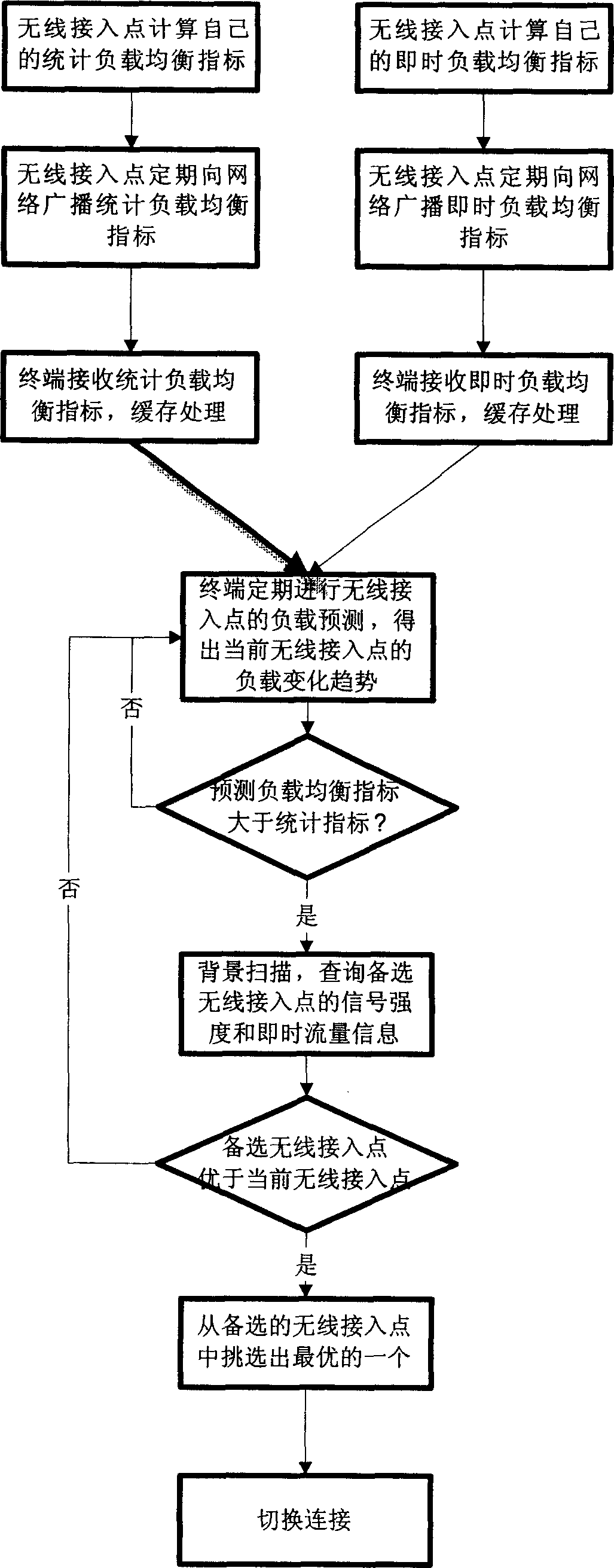
[0023] combine figure 2 , a specific implementation method of the present invention comprises the following steps:

[0024] 1. The wireless access point calculates its real-time load balancing index and statistical load balancing index. The real-time load balancing index at least includes: the number of terminals connected to the wireless access point, and the traffic of the wireless access point. Statistical load balancing indicators include at least: the maximum number of connected sites of wireless access points, the maximum flow level of wireless access points, and the average QoS requir...


PUM


Abstract

This invention discloses a load balance mode of a WLAN, which broadcasts periodically to transmit load information to terminals by radio access points and terminals forecast the change trend of loads of the radio access points to decide their switch behavior. Advantage: 1, since load information of radio access points is correlative on time, the terminal can forecast the change trend of radio access points to decide if it switches to other access points or maintains the current connection, when there is not burst peak to the load of the radio access point, the terminal can maintain the current connection to avoid switch because of the intensity of signals, 2, the terminal can make switch action before the coming of laod peak so as to reduce risk brought with switch.

Description

technical field [0001] The invention relates to a wireless local area network system in the communication field, in particular to a method for realizing load balancing in the wireless local area network. Background technique [0002] WLAN (Wireless Local Area Network) refers to the application of wireless communication technology to interconnect computer equipment to form a network system that can communicate with each other and realize resource sharing. In a WLAN network environment, an extended service group system consists of one or more basic service groups and distribution systems connecting these basic service groups, and each basic service group includes a wireless access point device. The extended service set is distinguished by ESSID (extended service set identification number), and the wireless access point is distinguished by BSSID (basic service set identification number). The terminal obtains the information of the extended service group and the basic service g...

Claims


Application Information

Patent Timeline
IPC IPC(8): H04L12/28
Inventor 王彬李峰李杰马凤国邰春玲
Owner ZTE CORP
Learn More