
Liquid crystal display equipment and GOA circuit

A liquid crystal display and circuit technology, which is used in static indicators, digital memory information, instruments, etc., to achieve the advantage of narrow frame design and reduce space.

Active Publication Date: 2016-03-16
TCL CHINA STAR OPTOELECTRONICS TECH CO LTD
View PDF8 Cites 6 Cited by
  • Summary
  • Abstract
  • Description
  • Claims
  • Application Information

AI Technical Summary

Problems solved by technology

When the panel adopts a high PPI design, due to the substantial increase in the number of gate lines, the maximum space height that can be occupied by each level of GOA circuit will decrease, and it is often necessary to increase the width of the wiring area during design, which will cause The panel peripheral (Border) area becomes wider, and the width of the Border area is sacrificed in exchange for wiring space, which is very unfavorable to the current popular narrow border design

Method used


Image

  • Liquid crystal display equipment and GOA circuit
  • Liquid crystal display equipment and GOA circuit
  • Liquid crystal display equipment and GOA circuit

Examples


Embodiment Construction

[0032] The following descriptions of the various embodiments refer to the accompanying drawings to illustrate specific embodiments in which the present invention can be practiced. The directional terms mentioned in the present invention, such as "up", "down", "front", "back", "left", "right", "inside", "outside", "side", etc., are for reference only The orientation of the attached schema. Therefore, the directional terms used are used to illustrate and understand the present invention, but not to limit the present invention.

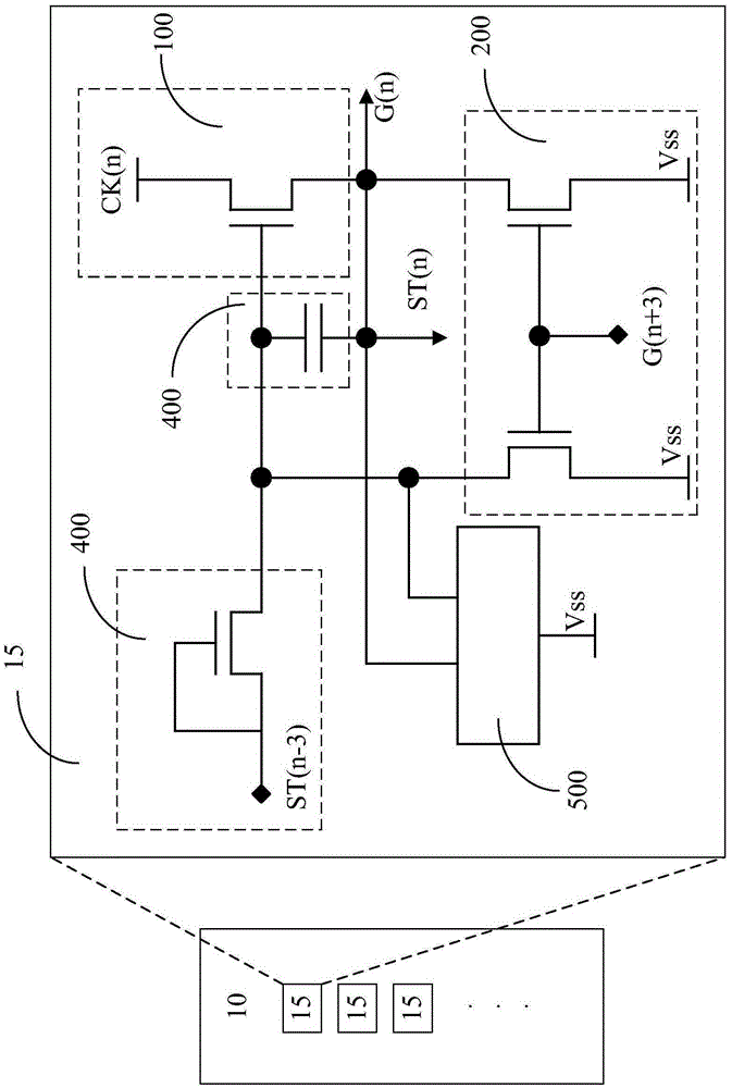
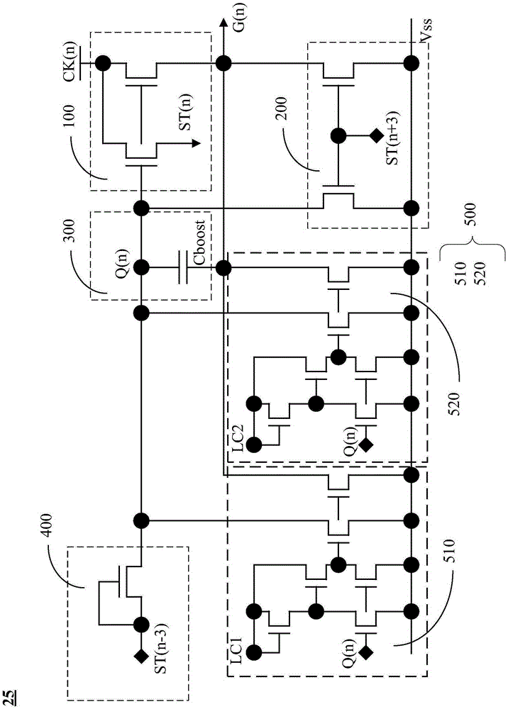
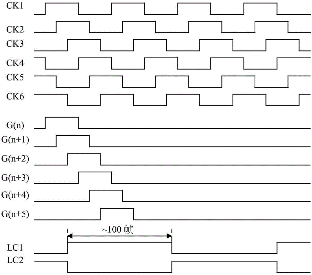
[0033] Figure 4 , is a structural diagram of the GOA circuit 30 of the first preferred embodiment of the present invention. The GOA circuit 30 includes a plurality of GOA units 35 cascaded with each other to form a multi-level GOA unit 35 . The nth level GOA unit 35 charges a corresponding n scan line G(n). The nth level GOA unit 35 includes a pull-down hold circuit 500 , a pull-up circuit 400 , a bootstrap capacitor circuit 300 , a pull-down circui...


PUM


Abstract

The invention discloses a gate driver on array (GOA) circuit used for liquid crystal display equipment. The liquid crystal display equipment comprises multiple scan lines. The GOA circuit comprises cascaded multiple GOA units. The nth GOA unit controls charging to the nth scan line. The nth GOA unit comprises a pull-down maintenance circuit, a pull-up circuit, a bootstrap capacitance circuit, a pull-down circuit and a clock circuit. The pull-down maintenance circuit comprises a first transistor, a second transistor, a third transistor and a fourth transistor. The liquid crystal display equipment and the GOA circuit aim at enhancing stability of grid signal points and reducing use of the transistors.

Description

【Technical field】 [0001] The invention relates to the technical field of liquid crystal display, in particular to a GOA (Gate Driver On Array, array substrate row scanning drive) circuit for liquid crystal display equipment. 【Background technique】 [0002] With the increasing popularity of narrow bezel design, the peripheral space of panel design is gradually compressed. In traditional GOA circuit design, the wiring space height h of each level of GOA circuit is consistent with the corresponding pixel size, and now it is 4k or higher. With the gradual popularization of PPI (pixel perinch) products, the pixel size is getting smaller and smaller, and the height of the space left for GOA circuit wiring is also reduced. Due to the height limit, only a larger width can be used for wiring. To make up, it is very detrimental to the design of the narrow frame. [0003] The gate signal point Q(n) is a very important potential in the GOA circuit. When the gate signal point Q(n) is at...

Claims


Application Information

Patent Timeline
Patent Type & Authority Applications(China)
IPC IPC(8): G09G3/36
CPCG09G3/3674G11C19/28G09G2310/0267G09G2310/0286G09G3/3648G09G2300/08G09G2310/08
Inventor 杜鹏
Owner TCL CHINA STAR OPTOELECTRONICS TECH CO LTD
Learn More