Chip card clamping mechanism

A chip card and card slot technology, which is applied to the structure of telephone sets, electrical components, transmission systems, etc., can solve problems such as difficult chip card removal, and achieve the effect of convenient operation

Inactive Publication Date: 2016-03-16
FUTAIHUA PRECISION ELECTRONICS ZHENGZHOU +1
View PDF4 Cites 2 Cited by
  • Summary
  • Abstract
  • Description
  • Claims
  • Application Information

AI Technical Summary

Problems solved by technology

However, when the chip card needs to be replaced or repaired, it is usually difficult to remove the chip card from the electronic device due to the tight installation

Method used


Image

  • Chip card clamping mechanism
  • Chip card clamping mechanism
  • Chip card clamping mechanism

Examples


Embodiment Construction

[0014] The chip card holding mechanism 100 provided by the present invention will be further described in detail below with reference to the accompanying drawings and embodiments.

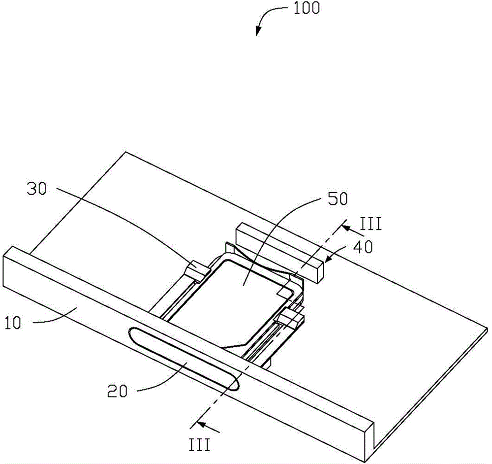
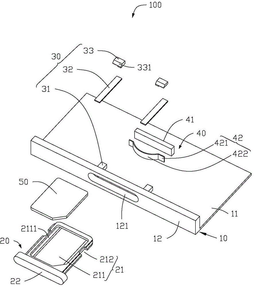
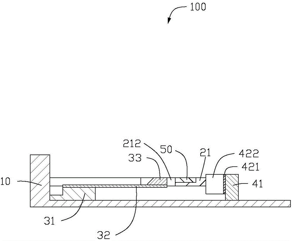
[0015] Please refer to figure 1 , the chip card holding mechanism 100 of the embodiment of the present invention is applied to a portable electronic device, and includes a housing 10 , a tray 20 , two holding components 30 , an ejecting component 40 and a SIM card 50 carried on the tray 20 . Two clamping components 30 are respectively clamped on both sides of the tray 20 for fixing the tray 20 in the casing 10; The tray 20 is pushed out from the housing 10 . To save space, other functional modules of the portable electronic device, such as circuit boards, backlight modules, etc., are not described.

[0016] Please refer to figure 2 , the casing 10 includes a bottom plate 11 and a side frame 12 . The bottom plate 11 is generally in the shape of a rectangular plate, and the side frame 12 extends...


PUM


Abstract

The invention discloses a chip card clamping mechanism, and the mechanism comprises a housing and a tray for supporting a chip card. The housing is provided with a jack, and the tray is slidingly disposed in the housing through the jack. The tray comprises a supporting part and a pushing part connected to one end of the supporting part, wherein two sides of the supporting part are provided with clamping grooves. The mechanism also comprises clamping assemblies disposed in the housing, a pop-out assembly, and a magnet located outside the housing. The clamping assemblies are disposed at two sides of the jack, and the pop-out assembly is opposite to the jack and is used for abutting against the tray inserted in the hosing. The clamping assemblies are mechanically clamped in the clamping grooves of the supporting parts, so as to fix the tray. The magnet is used for acting on the clamping assemblies so as to eliminate the mechanical coupling between the clamping assemblies and the clamping grooves. An elastic assembly elastically abuts against the supporting part, so as to enable the tray to be pushed out from the housing. The mechanism is convenient for the replacement of the chip card, and is convenient to operate.

Description

technical field [0001] The invention relates to a holding mechanism for accommodating and holding a chip card. Background technique [0002] Recently, with the rapid development of the mobile communication industry, the use of various portable electronic devices such as mobile phones and personal digital assistants (PDAs) has become very popular. As the functions of these portable electronic devices increase day by day, there are more and more chip cards used to store memory on these electronic devices, such as SIM cards (subscriber identity module card, customer identification module card), memory cards, IC cards (integrated circuit card) , integrated circuit card), SD card (secure digital memory card) and other cards. In order to facilitate the installation and disassembly of this type of chip card, the above-mentioned electronic equipment is generally equipped with a card connector. The contact terminals of the card connector are elastically pressed against the contact ...

Claims


Application Information

Patent Timeline
Patent Type & Authority Applications(China)
IPC IPC(8): H01R12/71H01R13/627H01R13/639H04M1/02
CPCH04B1/3818
Inventor 章绍汉
Owner FUTAIHUA PRECISION ELECTRONICS ZHENGZHOU
Why Eureka
Try Eureka