Automatic assembling technology for LED filament lamp

A technology for LED filament lamps and assembly processes, which is applied in the direction of lighting devices, light sources, semiconductor devices of light-emitting elements, etc., can solve problems such as low welding strength, low assembly efficiency of LED filament lamps, and complicated welding processes, so as to improve assembly efficiency, The effect of reducing the probability of assembly errors and ensuring reliability

Inactive Publication Date: 2018-06-12
NINGBO KLITE ELECTRIC MFG
View PDF7 Cites 2 Cited by
  • Summary
  • Abstract
  • Description
  • Claims
  • Application Information

AI Technical Summary

Problems solved by technology

[0005] The invention aims to overcome the problems of complicated LED filament welding process, low welding strength, and low assembly efficiency of LED filament lamps in the prior art, and provides a method that can

Method used


Image

  • Automatic assembling technology for LED filament lamp
  • Automatic assembling technology for LED filament lamp
  • Automatic assembling technology for LED filament lamp

Examples


Embodiment 1

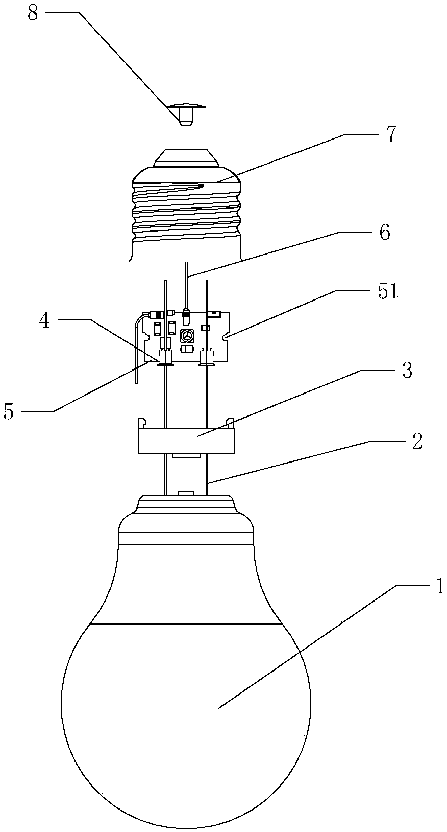
[0040] like figure 1 , Figure 3-7 In the shown embodiment, an LED filament lamp automatic assembly process, the specific flow of the assembly process is as follows:

[0041] The first station: first fix the glass bulb 1 in the fixture, then straighten the filament wire 2 with a robot, and then flow the fixed glass bulb 1 and the straightened filament wire 2 into the second station;

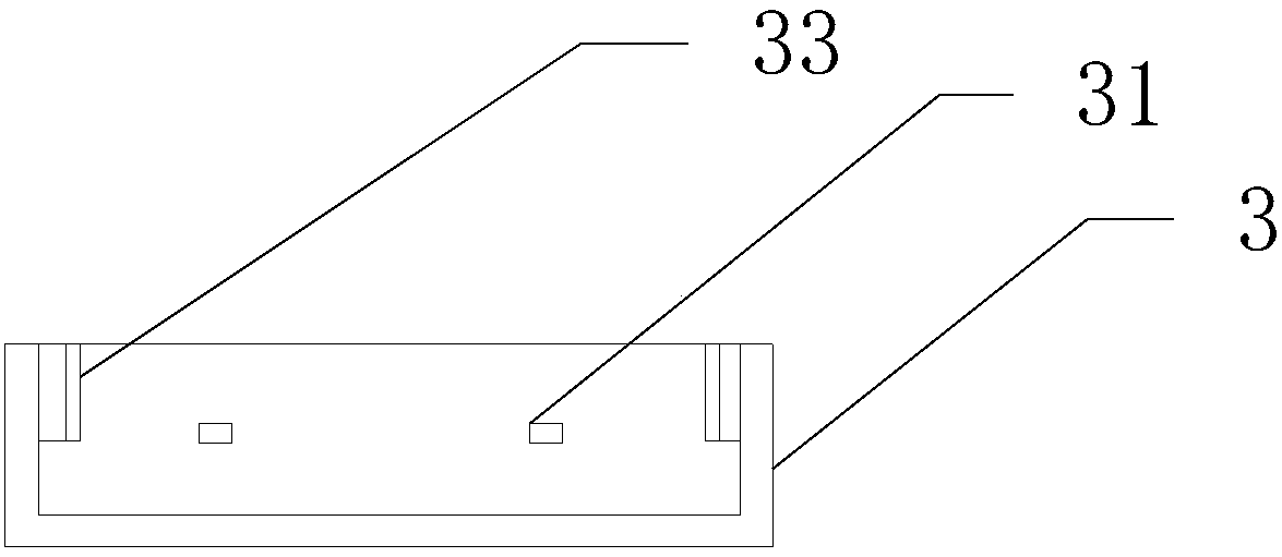
[0042]The second station: Use mechanical claws to grab the plastic support 3, pass the straightened filament wire 2 flowing in from the first station through the filament hole 31 in the plastic support 3, and place the plastic support 3 on the glass bulb 1 fixedly connected, and then flow into the third station; wherein the bottom end of the plastic support 3 is provided with a support buckle 32, and the end of the glass bulb 1 is provided with a support slot 13 matching the support buckle 32, and the support snaps Buckle 32 cooperates with bracket slot 13 so that plastic bracket 3 is fixedly c...

Embodiment 2

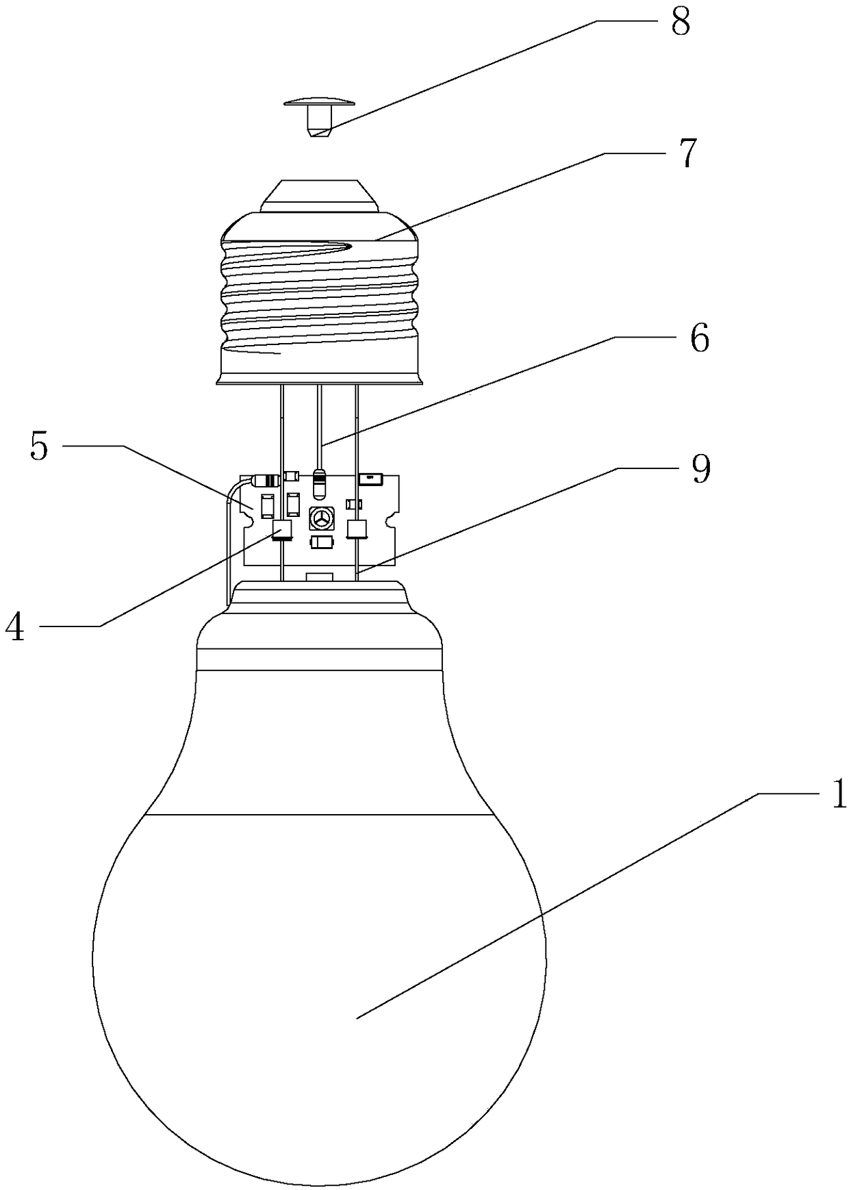
[0047] like figure 2 , Figure 5-7 In the shown embodiment, an LED filament lamp automatic assembly process, the specific flow of the assembly process is as follows:

[0048] The first station: first fix the glass bulb 1 in the fixture, and then flow into the second station;

[0049] The second station: manually weld the connector 4 to the drive assembly 5, then fix one end of the hard filament 9 to the connector 4, extend the other end into the glass bulb 1 and fix it, and cut off the excess The hard filament 9, then the whole flows into the third station;

[0050] The third station: Use mechanical claws to grab the lamp cap 7, apply glue inside the lamp cap 7, fix the lamp cap 7 and the glass bulb 1 to form a whole, cut off the redundant output line 6, and then install the lamp cap The thumbtack 8 flows into the fourth station; the end of the lamp cap 7 near the glass bulb 1 is provided with a lamp cap buckle 71 passing through the lamp cap 7, and the number of the lamp ...


PUM


Abstract

The invention discloses an automatic assembling technology for an LED filament lamp. All parts of the LED filament lamp pass through corresponding stations, and finally an LED filament lamp finished product is assembled. Due to the fact that an assembling production line in the mode of an assembly line is used in the automatic assembling technology, different assembling processes are processed onall the stations, automatic machine claws are used as the main processing means during the period, manual work serves as the auxiliary means, and therefore the whole assembling efficiency can be effectively improved, assembling time is shortened and assembling error probability is lowered. Meanwhile, a lamp filament and a driving assembly are connected through connectors in the assembling process,and the problems of being high in lamp body reject ratio and high in cost caused by infirm welding between the lamp filament and the driving assembly, long welding time and low assembling efficiencyare reduced. Hence, the automatic assembling technology for the LED filament lamp has the following beneficial effects that (1) difficulties in the assembling process are reduced; (2) the lamp filament and the driving assembly are tightly connected; and (3) the whole assembling efficiency is high.

Description

technical field [0001] The invention relates to a lamp assembly process, in particular to an automatic assembly process for LED filament lamps. Background technique [0002] The emergence of tungsten filament incandescent lamps in the 19th century led the world into the era of artificial lighting. Since the emergence of the revolutionary new light source LED in the 20th century, it has quickly become popular in the lighting market due to its advantages of energy saving, environmental protection and long life. LED has become the mainstream lighting source in the future and is widely used in commercial lighting, industrial lighting, outdoor lighting, etc. However, the development of civilian lighting is relatively slow. For many people, LED lights are a new type of light source that has never been heard of. In 2008, Japan’s Ushio Light Source launched a bulb-type lamp “LED Filament Bulb” that uses an incandescent lamp prototype to configure LEDs. The emergence of this phenome...

Claims


Application Information

Patent Timeline
IPC IPC(8): F21K9/90F21Y115/10
CPCF21K9/90F21Y2115/10
Inventor 朱斌
Owner NINGBO KLITE ELECTRIC MFG
Why Eureka
Try Eureka