Voltage reactive power control method and system based on reactive power compensation device

A technology of voltage and reactive power control and compensation device, which is applied in reactive power compensation, reactive power adjustment/elimination/compensation, circuit devices, etc. problems, to achieve the effect of meeting complex needs

Active Publication Date: 2018-09-11
GUANGDONG POWER GRID CO LTD SHANTOU POWER SUPPLY BUREAU
View PDF2 Cites 0 Cited by
  • Summary
  • Abstract
  • Description
  • Claims
  • Application Information

AI Technical Summary

Problems solved by technology

However, when the line is too long or the load fluctuates greatly, the regulation of voltage / reactive power cannot meet the requirements of power quality only by changing the transformer tap or parallel capacitance
[0005] For the fixed capacitors commonly used in the current distribution network, when performing voltage and reactive power control, they can only be put in or removed in groups, and their ability to adjust voltage and reactive power is limited.
Most of the TCR (Thyristor Controlled Reactor) type SVC (Static Var Compensator), which are more widely used, only take power factor or a certain level of voltage or power factor as the target, and the control target is relatively single, and the system is not fully considered. complexity, it is difficult to achieve better multi-objective optimal control

Method used


Image

  • Voltage reactive power control method and system based on reactive power compensation device
  • Voltage reactive power control method and system based on reactive power compensation device
  • Voltage reactive power control method and system based on reactive power compensation device

Examples


Embodiment Construction

[0021] In order to make the purpose, technical solution and advantages of the present invention clearer, the present invention will be further described in detail below in conjunction with the accompanying drawings.

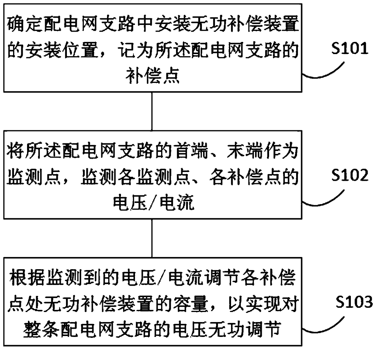
[0022] Please refer to the attached figure 1 , is a schematic flowchart of a voltage and reactive power control method based on a reactive power compensation device in an embodiment, mainly including steps S101 to S103, and detailed descriptions are as follows:

[0023] S101. Determine the installation position of the reactive power compensation device in the branch circuit of the distribution network, and record it as the compensation point of the branch circuit of the distribution network.

[0024] In the embodiment of the present invention, the reactive power compensation device can be a device for reactive power compensation such as a passive power filter, an active power filter, a static var compensation device, and the present invention does not need to mak...


PUM


Abstract

The invention provides a voltage reactive control method and a voltage reactive control system based on a reactive compensation device. The method comprises the following steps of determining an installation position for installing the reactive compensation device in a power distribution network branch, recording the installation position as a compensation point of the power distribution network branch; taking a head end and a tail end of the power distribution network branch as monitoring points, and monitoring voltage / current of each monitoring point and voltage / current of each compensation point; regulating capacity of the reactive compensation device at each compensation point according to the monitored voltage / current, thereby realizing voltage reactive regulation on the whole power distribution network branch. According to the invention, voltage / current of each monitoring point and voltage / current of each compensation point of the power distribution network branch are monitored, and capacity of the reactive compensation device at each compensation point is regulated according to the monitoring result, thus, voltage reactive compensation for multiple parts of the power distribution network branch is realized, and complex needs of an electric system are satisfied.

Description

technical field [0001] The invention relates to the field of power systems, in particular to a voltage and reactive power control method based on a reactive power compensation device and a system thereof. Background technique [0002] Voltage quality is an important index to measure power quality, which is closely related to people's production and life. Stable and high-quality power quality has always been the goal pursued by people. With the advancement of modern science and technology and the improvement of automation, the requirements for the quality of power supply of power systems are also getting higher and higher. Unstable power quality will bring great inconvenience to customers; ensuring qualified power quality is also a prerequisite for safe production of users and normal operation of electrical equipment. If the system runs beyond the upper limit for a long time, it will shorten the life of electrical equipment and reduce the use efficiency; if the system runs b...

Claims


Application Information

Patent Timeline
Patent Type & Authority Patents(China)
IPC IPC(8): H02J3/16H02J3/18
CPCH02J3/16H02J3/1864Y02E40/30
Inventor 李清波潘靖袁佳歆
Owner GUANGDONG POWER GRID CO LTD SHANTOU POWER SUPPLY BUREAU
Why Eureka
Try Eureka