Portal imaging during radiotherapy

一种成像装置、设备的技术,应用在射野成像领域,能够解决不常见等问题

Active Publication Date: 2016-03-23
ELEKTA AB
View PDF5 Cites 8 Cited by
  • Summary
  • Abstract
  • Description
  • Claims
  • Application Information

AI Technical Summary

Problems solved by technology

However, this is rarely a problem in obtaining therapeutic images, as large field sizes are uncommon and will therefore generally fall within its limits on the panel

Method used


Image

  • Portal imaging during radiotherapy
  • Portal imaging during radiotherapy
  • Portal imaging during radiotherapy

Examples


Embodiment Construction

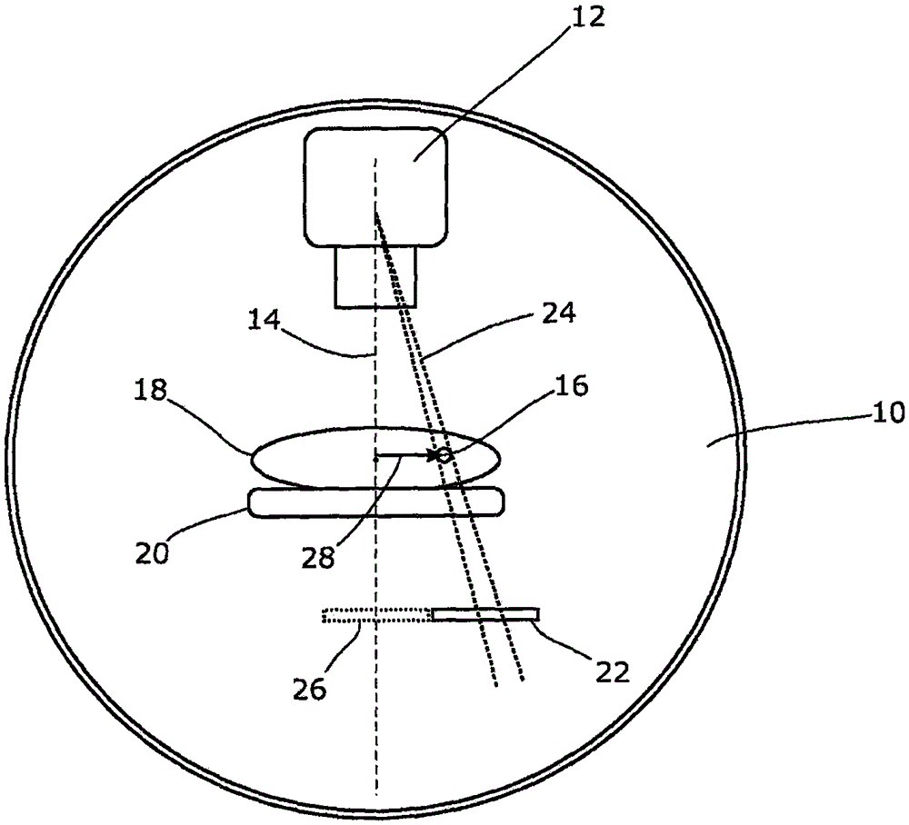
[0024] As mentioned above, the field size of current EPIDs is larger than most practical dose shapes but smaller than the maximum aperture of most MLCs. We have realized that this limitation becomes a problem when EPID is used for field dosimetry or to capture dynamic MLC video under certain therapeutic conditions. As an example, we propose to discuss Volume Modulated Arc Therapy (VMAT) delivery to off-axis targets such as tumors present in a chest or lung. However this is not the only example and the invention is applicable in other contexts.

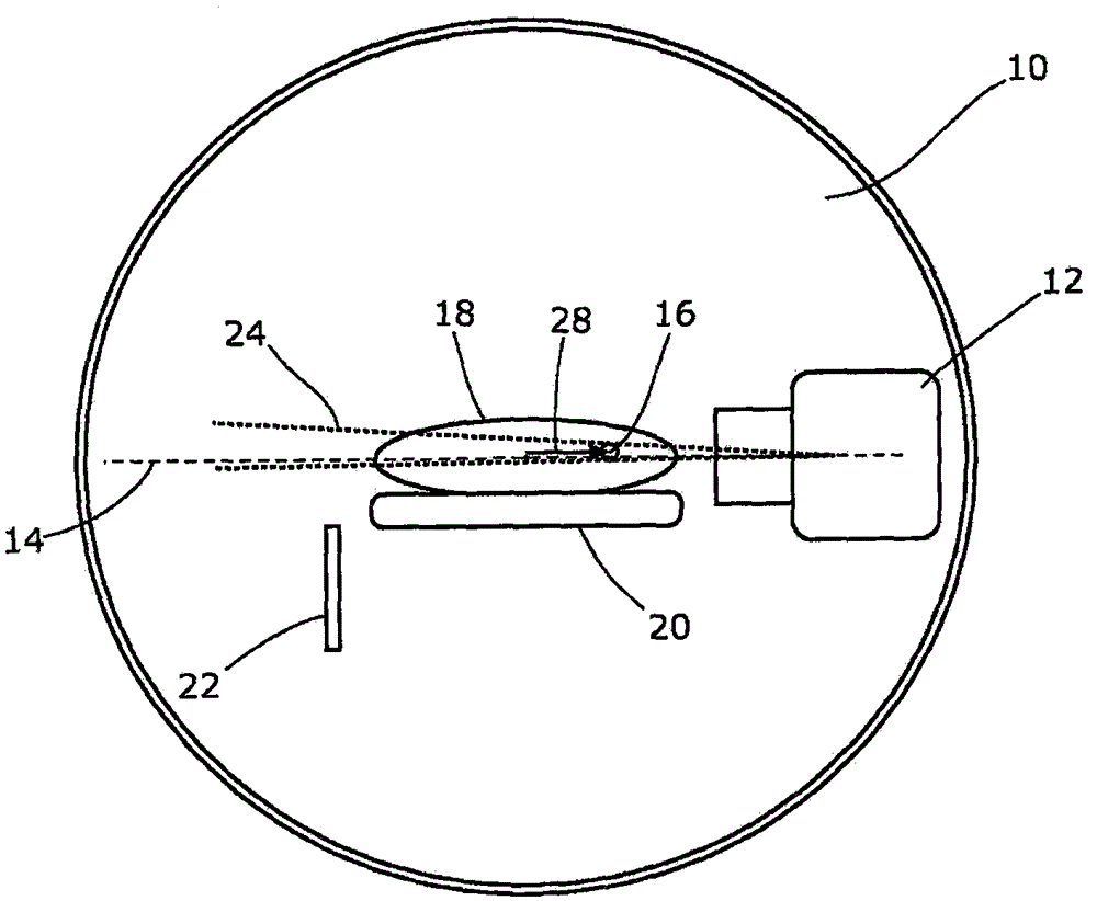
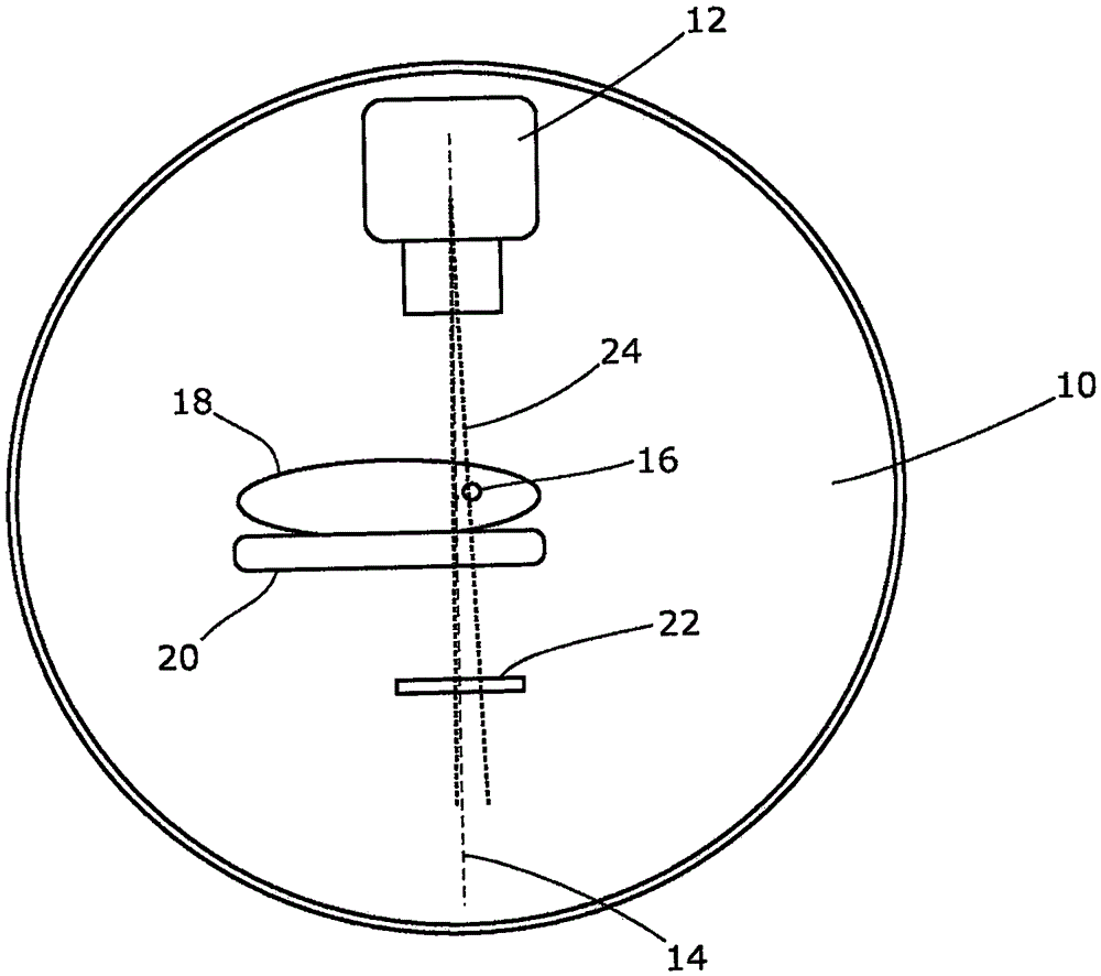
[0025] figure 1 shows this situation. The rotatable frame 10 is provided in an upright orientation, possibly recessed in a wall or protruding through a false wall. It is rotatable about a horizontal axis in the form of a drum; figure 1 is the view along that axis. The gantry 10 carries a radiation source 12 capable of emitting a collimated beam of therapeutic ionizing radiation about a central axis 14 that intersects a horizontal ...


PUM


Abstract

A radiotherapy apparatus comprises: a source for producing a beam of ionising radiation along an axis, the beam covering a maximum aperture of the source; a collimator for collimating the beam to produce a collimated beam covering a sub-part of the maximum aperture; a patient support positioned in the path of the beam; a rotatable gantry, on which the source is mounted, for rotating the source around the patient support thereby to deliver the beam from a range of directions; an imaging device located opposite the source and with the patient support between the source and the imaging device, and mounted on the gantry via a drive member allowing translational motion of the imaging device in at least one direction perpendicular to the axis; and a control unit adapted to control the drive member to move the imaging device within the maximum aperture and maintain coincidence between the imaging device and the sub-part of the maximum aperture. Accordingly, the EPID can be moved during the treatment in order to maintain the collimated field of the radiation beam within the bounds of the EPID. This ensures that the image is valid and prevents damage to the EPID as a result of exposure of more sensitive (or less shielded) parts to the beam.

Description

technical field [0001] The present invention seeks to improve existing methods of portal imaging during radiotherapy treatments. Background technique [0002] Radiation therapy is the treatment of lesions, such as tumors, using ionizing radiation, such as high-energy x-rays. This radiation interferes with cellular processes within the tumor and can lead to cell death. In order not to harm healthy tissue (such as the skin or organs adjacent to the tumor, or through which the radiation needs to pass in order to treat the tumor), the shaped radiation beam is aimed from several different angles to cross at the tumor, so that the peak dose Delivery to the tumor area and lower doses elsewhere. [0003] To allow delivery of radiation from several angles, the radiation source is typically mounted at the end of a cantilever projecting from the rotatable gantry. The gantry has a horizontal axis of rotation and the radiation source has a field of view with its central axis perpendic...

Claims


Application Information

Patent Timeline
Patent Type & Authority Applications(China)
IPC IPC(8): A61N5/10
CPCA61N5/1047A61N2005/1054A61B6/032A61N5/1049A61N5/1048A61N5/1071A61N5/1036A61N5/107A61N5/1081A61N5/1083A61N2005/1074
Inventor J·阿伦C·温菲尔德
Owner ELEKTA AB
Why Eureka
Try Eureka