Electronic component storage box

A technology of electronic components and storage boxes, applied in the field of storage boxes, can solve problems such as low efficiency, waste of labor, and restricted production capacity, and achieve the effect of large storage quantity, simple structure, and high storage efficiency

Inactive Publication Date: 2016-03-23
SUZHOU YUANSHUO PRECISION MOLD
View PDF4 Cites 4 Cited by
  • Summary
  • Abstract
  • Description
  • Claims
  • Application Information

AI Technical Summary

Problems solved by technology

Therefore, in the process of continuous arranging and breaking up, a lot of labor is wasted in vain, and the efficiency is low, which seriously restricts the production capacity

Method used


Image

  • Electronic component storage box
  • Electronic component storage box
  • Electronic component storage box

Examples


Embodiment 1

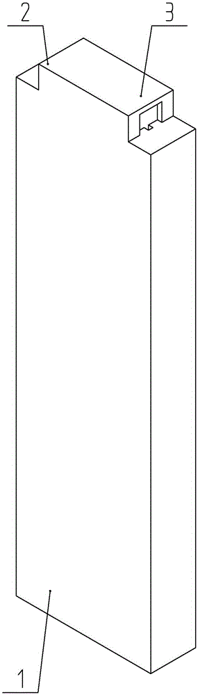
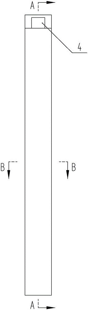
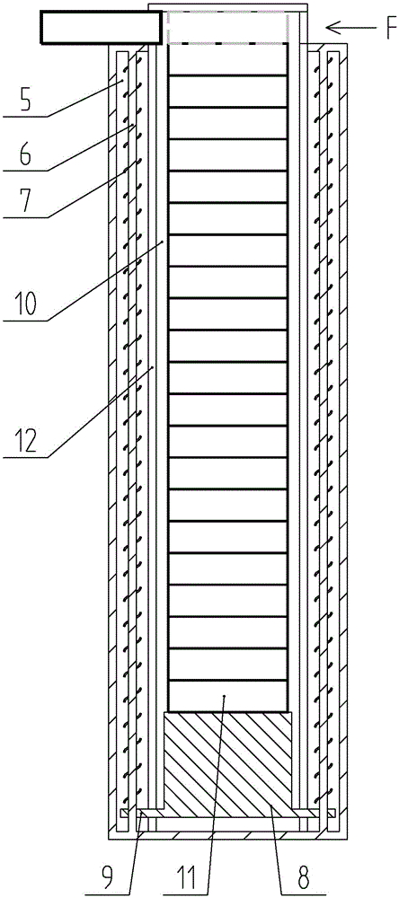
[0018] Such as Figures 1 to 4 As shown, in this embodiment, the so-called height direction refers to the direction where the longer side in the figure is located. The storage box can be used standing up as shown in the picture, or it can be used horizontally. An electronic component storage box includes a casing 1 made of hard plastic injection molding and having an inner cavity. Two side plates 12 parallel to each other are arranged in the shell 1 along the height direction to divide the inner cavity into a storage chamber 10 and two side chambers 5 located on both sides of the storage chamber 10 . A slot extending along the height direction is opened on the side plate 12 , and the slot connects the receiving chamber 10 and the side chamber 5 with each other. The top of the casing 1 is provided with a convex shell 2 , the interior of the convex shell 2 is integrated with the accommodation chamber 10 , and the left and right ends of the convex shell 2 communicate with the o...

Embodiment 2

[0020] Different from Embodiment 1, in this embodiment, the movable baffle 3 is detachably installed on the top of the convex shell 2 through bolts, so as to realize the opening and closing of the top of the convex shell 2 .

[0021] When storing the workpieces 11 , the movable baffle 3 on the top of the convex shell 2 is opened to expose the accommodation chamber 10 , and the workpieces 11 enter the accommodation chamber 10 side by side one by one. As the number of workpieces 11 increases, the lifting platform 8 gradually descends and makes the spring 7 gradually have greater potential energy. When the accommodating chamber 10 has been filled with workpieces 11, it is only necessary to close and lock the movable baffle 3.

[0022] When picking up the piece, a force F aligned with the pick-up opening 4 is applied through the thimble (driven by the cylinder), and the workpiece 11 (the first workpiece 11 ) located at the pick-up opening 4 is pushed out. Under the action of the ...


PUM


Abstract

The invention discloses an electronic component storage box. The electronic component storage box comprises a shell provided with an inner cavity. Two parallel side plates are arranged in the height direction in the shell and divide the inner cavity into a containing chamber and two side chambers located on the two sides of the containing chamber. Gaps extending in the height direction are formed in the side plates. A convex shell is arranged at the top of the shell. The interior of the convex shell is communicated with the containing chamber. The left end and the right end of the convex shell are opened. A movable baffle with the covering function is arranged at the top of the convex shell. Each side chamber is provided with a spring. A lifting table is arranged in the containing chamber. The left end and the right end of the lifting table extend outwards to form connecting arms. The connecting arms penetrate through the gaps and extend into the corresponding side chambers. One ends of the springs are connected with the tops of the side chambers, and the other ends of the springs are connected with the corresponding connecting arms. The electronic component storage box has the beneficial effects that the storage number is large and the storage efficiency is high; extra protection is provided for electronic components in the storage and transferring process of the electronic components, so that the electronic components are prevented from being damaged due to inter-collision and other reasons.

Description

technical field [0001] The invention relates to a storage box, in particular to an electronic component storage box used for storing and processing a plurality of tiny electronic components. Background technique [0002] Electronic components are small in size and irregular in shape, so there are many inconveniences in the process of processing and storage. Some electronic components with a cylindrical structure need to be positioned one by one on the station for processing during processing, and then neatly arranged one by one and placed in a special fixture (also known as a magazine) so as to be sent to the next process to continue processing. Therefore, in the process of continuous arranging and breaking up, a large amount of labor is wasted in vain, and the efficiency is low, which seriously restricts the production capacity. How to solve the above problems and design a device that facilitates the orderly storage of workpieces and the transfer between processes is an ur...

Claims


Application Information

Patent Timeline
Patent Type & Authority Applications(China)
IPC IPC(8): B65D85/86B65D83/00
CPCB65D83/00H05K13/0084
Inventor 何婷朱磊
Owner SUZHOU YUANSHUO PRECISION MOLD
Why Eureka
Try Eureka