Automatic dehydrating and oil returning system for siphoning type oil tank and oil returning method

An oil return system, siphon type technology, applied in the field of oil tank oil return system, can solve the problems of oil and water mixing together, unstable oil-water interface, etc., and achieve the effects of improving efficiency, long service life and avoiding damage

Active Publication Date: 2016-03-23
GUANGZHOU DAY WO AUTOMATION IND
View PDF11 Cites 3 Cited by
  • Summary
  • Abstract
  • Description
  • Claims
  • Application Information

AI Technical Summary

Problems solved by technology

[0004] In order to solve the technical problem of unstable oil-water interface and mixing of oil and water, the present invention provides a siphon type oil tank automatic dehydration oil return system and oil return method that completely isolates oil from air and has good sealing performance

Method used


Image

  • Automatic dehydrating and oil returning system for siphoning type oil tank and oil returning method
  • Automatic dehydrating and oil returning system for siphoning type oil tank and oil returning method
  • Automatic dehydrating and oil returning system for siphoning type oil tank and oil returning method

Examples


Embodiment 1

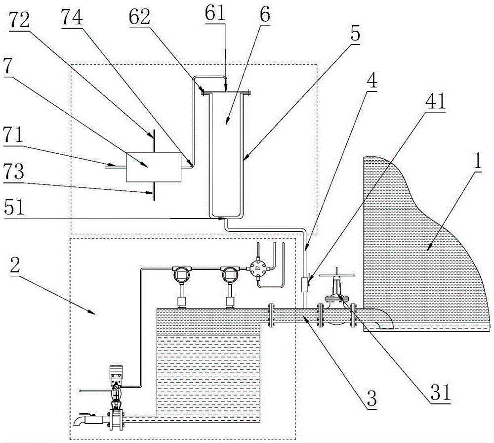
[0047] like figure 1 The siphon type oil tank automatic dehydration and oil return system of the present invention includes an oil tank 1, a dehydrator 2, a dehydration pipeline 3 for connecting the oil tank 1 and the dehydrator 2, and an oil return system. The oil return system passes through the connecting pipeline 4 communicates with the dehydration pipeline 3 , and the connection port between the connection pipeline 4 and the dehydration pipeline 3 is arranged on the top wall of the dehydration pipeline 3 .

[0048] The oil return system includes a buffer tank 5, a soft capsule 6, a control device 7 for controlling the increase or decrease of the air pressure in the buffer tank, the soft capsule 6 is provided with an air chamber, and the soft capsule 6 is arranged on the In the buffer tank 5 , the buffer tank 5 and the soft capsule 6 are hermetically connected through a mounting flange 62 , the soft capsule 6 is provided with an air filling port 61 , and the buffer tank 5 ...

Embodiment 2

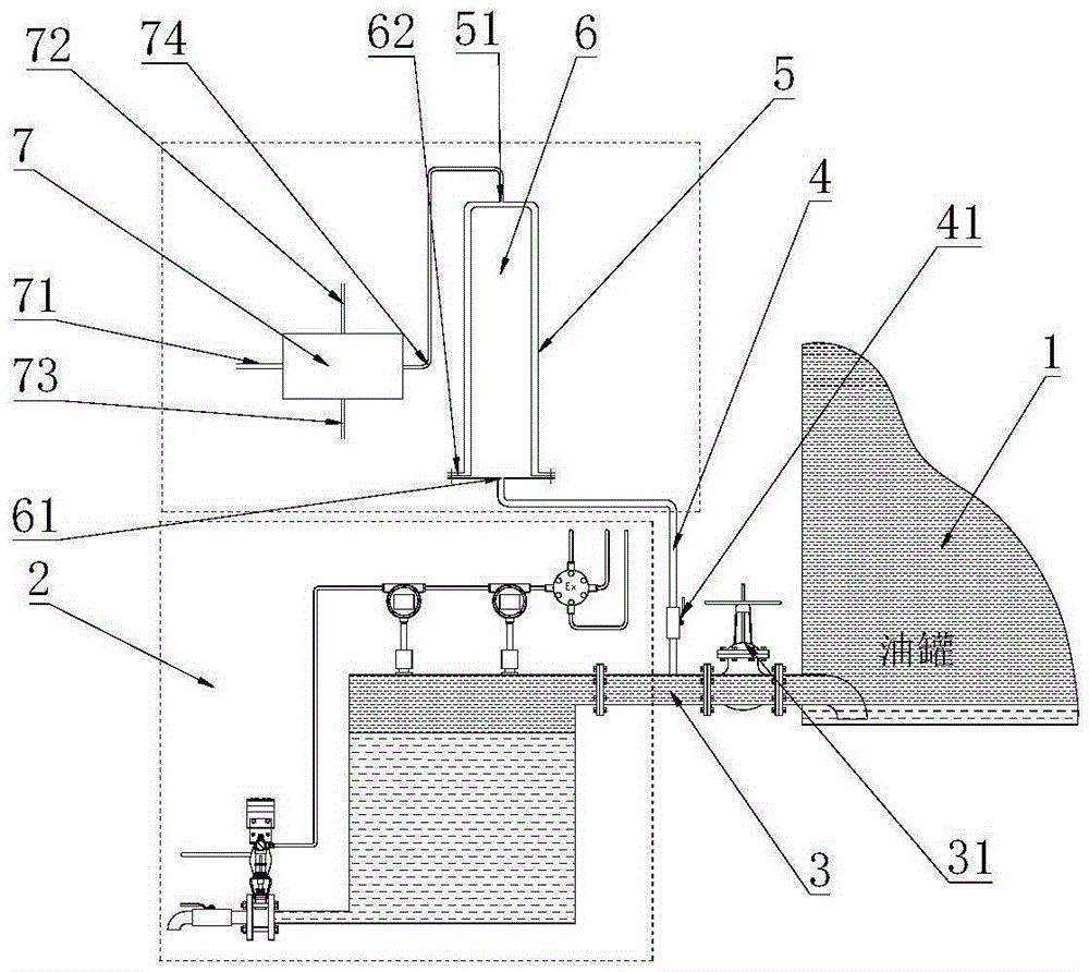
[0058] like figure 2 As shown, the siphon type oil tank automatic dehydration oil return system described in this embodiment, except for the connection direction of the oil return system, other structures and working principles are the same as those in the first embodiment. The inflation port 61 of the soft capsule 6 is connected to the connecting pipe 4 , and the gas outlet 51 of the buffer tank 5 is connected to the control channel 74 of the pressure controller 7 .

[0059] A method for automatically dehydrating and returning oil to a siphon type oil tank, comprising the following steps:

[0060] S1. The controller 73 controls the conduction of the air intake channel 71, inflates the buffer tank 5, squeezes the soft capsule 6, makes the soft capsule 6 shrink, and discharges the oil in the soft capsule 6 to the oil tank 1.

[0061] S2. The controller 73 closes the air intake channel 71, opens the exhaust channel 72, and discharges the gas in the buffer tank 5, the pressure ...

Embodiment 3

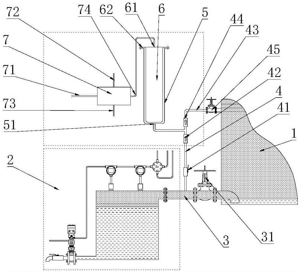
[0066] like image 3 As shown, the siphon type oil tank automatic dehydration oil return system described in this embodiment, except for the oil return channel of the oil return system, other structures and working principles are the same as those in the first embodiment. The control passage 4 is provided with a first one-way valve 42, and the first one-way valve 42 leads from the deoiling passage to the oil return system. It also includes an oil return pipeline 43. One end of the oil return pipeline 43 is arranged on the control channel 4 between the first one-way valve 42 and the buffer tank 5, and the other end is connected to the oil tank 1. On the oil return pipeline 43 A second one-way valve 44 is provided, and the second one-way valve 44 leads from the buffer tank 5 to the oil tank 1 . The oil return passage 43 is provided with an oil return switch valve 45 .

[0067] A method for automatic dehydration and oil return of a siphon type oil tank, the steps are as follows...


PUM


Abstract

The invention discloses an automatic dehydrating and oil returning system for a siphoning type oil tank and an oil returning method. The automatic dehydrating and oil returning system comprises an oil tank, a dehydrator, a dehydrating pipeline for connecting the oil tank and the dehydrator and an oil returning system, wherein the oil returning system is connected with the dehydrating pipeline through a connecting pipeline; a connecting hole of the connecting pipeline and the dehydrating pipeline is formed in the top wall of the dehydrating pipeline; the oil returning system is composed of a buffer tank, a soft capsule and a controlling device; an inflation cavity and an inflation hole are formed in the soft capsule; the buffer tank seals the soft capsule in a tank body of the buffer tank; a gas outlet is formed in the buffer tank; and the controlling device is connected with the inflation cavity of the soft capsule or the gas outlet of the buffer tank. According to the automatic dehydrating and oil returning system disclosed by the invention, oil is isolated from air through the soft capsule and the sealed buffer tank, the deformation characteristics of the soft capsule is utilized, and the oil returning system is controlled to suck or discharge oil by changing the pressure in the soft capsule without a limitation of speed, so that the automatic dehydrating and oil returning system improves the oil returning efficiency and is safe and environment-friendly.

Description

technical field [0001] The invention belongs to the technical field of oil return systems for oil tanks, and in particular relates to a siphon type oil tank automatic dehydration oil return system and an oil return method. Background technique [0002] In order to meet the requirements of safety and environmental protection, an automatic dehydrator must be installed for oil tank dehydration. In order to ensure the continuity of dehydration, during the dehydration process, the oil entering the dehydrator must automatically return to the oil tank to continue dehydration. When the dehydration port of the storage tank is a siphon port, the oil in the dehydrator cannot automatically float back to the oil tank through the density difference, and the oil at the top of the dehydrator must be drawn back to the oil tank by external force. [0003] Patent No. 201420553227.4 discloses a breathing-type automatic dehydration and oil return system for siphon oil tanks, which uses water to ...

Claims


Application Information

Patent Timeline
Patent Type & Authority Applications(China)
IPC IPC(8): B65D88/54B65D90/32B01D17/032
CPCB01D17/0214B65D88/54B65D90/32
Inventor 韩德福李鹏
Owner GUANGZHOU DAY WO AUTOMATION IND
Why Eureka
Try Eureka