Vibration conveyor for automatic production

A technology for vibrating conveyors and conveying devices, which is applied in the direction of vibrating conveyors, conveyors, transportation and packaging, etc., and can solve problems such as easily damaged vibration devices and conveying devices, easily damaged frame structures, and poor shock absorption effect of the frame , to achieve uniform force, good reliability and good effect

Inactive Publication Date: 2016-03-23
黄丽
View PDF3 Cites 7 Cited by
  • Summary
  • Abstract
  • Description
  • Claims
  • Application Information

AI Technical Summary

Problems solved by technology

[0004] The existing frame is basically composed of columns, beams and longitudinal beams. Its main function is to support the vibrating device. However, since the vibrating device will generate frequent vibrations during operation, if the rack bracket is installed on the bottom surface and other supports, The shock absorption effect of the rack itself is poor, it is easy to damage the rack structure, and the damage to the support is also large.
In addition, if the height of the rack is high, when the vibration device is working, it is easy to cause the rack to tip over.
[0005] The existing vibrating device is in rigid contact with the conveying device, and it is easy to damage the vibrating device and the conveying device during the vibration process
[0006] The existing conveying device is mainly a trough. In order to carry the material, the trough is bent to form a storage cavity. However, because the trough is formed by bending, the trough is easily deformed.

Method used


Image

  • Vibration conveyor for automatic production
  • Vibration conveyor for automatic production
  • Vibration conveyor for automatic production

Examples


Embodiment Construction

[0029] The present invention will be further described in detail below in conjunction with the accompanying drawings and specific embodiments.

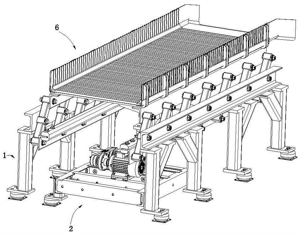
[0030] Such as Figure 1 to Figure 3 As shown, the vibrating conveyor for automatic production includes a frame 1 , a base 2 , a drive system 3 , a swing device 4 , a conveying support frame 5 and a conveying device 6 .

[0031] Such as Figure 1 to Figure 5 As shown, the rack 1 includes two rack assemblies 100 arranged symmetrically. The frame assembly 100 includes more than two sets of support column assemblies and beams 10 . Each set of supporting column assemblies includes two symmetrically arranged supporting members 11 .

[0032] Such as Figure 4 with Figure 5 As shown, the support member 11 includes a frame shock absorber 111 , a column 112 , a diagonal brace 113 and a solid column 114 .

[0033] Such as Figure 4 , Figure 5 with Image 6 As shown, the frame shock absorber 111 includes a shock absorber base 1111 , a...


PUM


Abstract

The invention discloses a vibration conveyor for automatic production. The vibration conveyor comprises a rack, a base, a driving system, a swinging device, a conveying supporting frame and a conveying device, wherein the base is arranged on the rack; the driving system is mounted on the base; the swinging device is hinged to the rack and driven by the driving system to swing; the conveying supporting frame is hinged to the swinging device, and the conveying device is arranged on the conveying supporting frame. According to the vibration conveyor adopting the aforementioned structure, the shock absorbing performance can be improved, and the supporting stability can be improved; the swinging device can swing uniformly, so that the swinging device can be protected, and as a result, the conveying device can be limited to deform.

Description

technical field [0001] The present invention relates to automated vibrating conveyors. Background technique [0002] At present, in order to realize continuous automatic production, conveyors are used in many places. The types of conveyors mainly include conveyor belt conveyors, conveyor roller conveyors and vibrating conveyors. The vibrating conveyor is a continuous conveying machine that uses a vibrator to vibrate the trough, so that the material in the trough slides or is thrown in a certain direction. [0003] Existing vibration conveyer mainly comprises frame, the vibrating device that is installed on the frame and is connected with vibrating device and is conveying device. [0004] The existing frame is basically composed of columns, beams and longitudinal beams. Its main function is to support the vibrating device. However, since the vibrating device will generate frequent vibrations during operation, if the rack bracket is installed on the bottom surface and other ...

Claims


Application Information

Patent Timeline
IPC IPC(8): B65G27/04B65G27/08B65G27/12
CPCB65G27/04B65G27/08B65G27/12
Inventor 黄丽
Owner 黄丽
Why Eureka
Try Eureka