Pallet box transferring device

A transfer device, pallet box technology, applied in transportation and packaging, conveyor objects, conveyors, etc., can solve the problems of small carrying load, large labor consumption, poor flexibility, etc., to improve load-bearing capacity and overcome labor-intensive problems. Effect

Active Publication Date: 2016-03-23
淮北市宇控信息技术有限公司
View PDF6 Cites 13 Cited by
  • Summary
  • Abstract
  • Description
  • Claims
  • Application Information

AI Technical Summary

Problems solved by technology

[0006] (2) It needs to consume a lot of labor, especially working in a hot outdoor environment, which greatly reduces the enthusiasm of the workers;
[0007] (3) Transshipment work for a long time will lead to a decrease in work efficiency
[0009] (1) The existing forklifts occupy a relatively large area, and multiple forklifts work at the same time, requiring a relatively spacious working environment
In actual work, some transshipment areas are relatively narrow, which is not conducive to multiple forklifts working at the same time;
[0010] (2) Existing forklifts generally can only fork out or push out pallet boxes, but cannot carry out unloading work for materials carried in pallets, and the flexibility is poor;
[0011] (3) The pallet box is usually supported by the fork. During the transfer process, the pallet box is easy to fall from the fork, and the stability of the fork is poor.
[0012] The pallet boxes produced under the prior art are usually of an integrated structure, that is, the pallet frame and the side panels are welded as a whole, and can only have a single load-bearing function, and the diversity of its functions needs to be improved
In addition, the storage board of the traditional pallet rack is generally a single-layer structure, and the load-carrying load is small; for the storage board of the double-layer structure, although it has a good bearing capacity, the cost is relatively expensive

Method used


Image

  • Pallet box transferring device
  • Pallet box transferring device
  • Pallet box transferring device

Examples


Embodiment Construction

[0046] The present invention will be described in detail below in conjunction with the accompanying drawings.

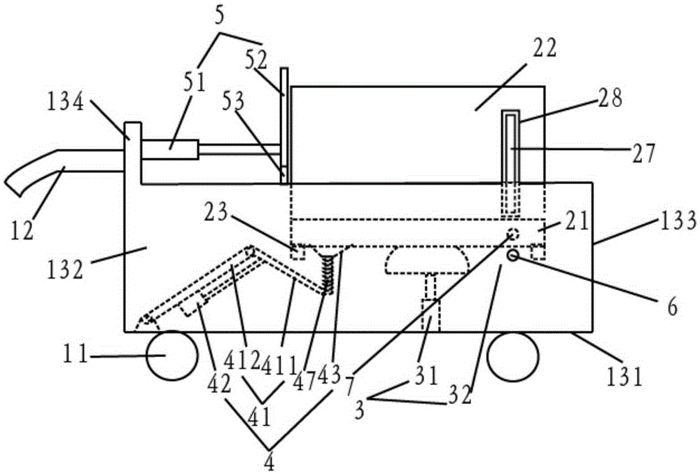
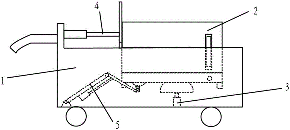
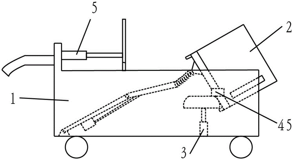
[0047] Such as Figure 1-3 As shown, this embodiment includes a transfer trolley 1 , a pallet box 2 , a lifting mechanism 3 , an overturning mechanism 4 and a pushing mechanism 5 .

[0048] The transfer trolley 1 includes several universal wheels 11, two handrails 12 and a top opening welded by a bottom plate 131, two side baffles 132, a front baffle 133, and a rear baffle 134, and the four sides and the bottom are closed. 1. A hollow cart body; the height of the front baffle 133 is lower than the height of the back baffle 134; the two armrests 12 are symmetrically arranged on the left and right ends of the outside of the back baffle 134; the The universal wheel 11 is arranged on the bottom of the bottom plate 131 .

[0049] Such as figure 1 , 5 , 6, 7, and 8, the pallet box 2 includes a pallet frame 21 and a side plate assembly 22, and several support plates 23 ...


PUM


Abstract

The invention discloses a pallet box transferring device. The pallet box transferring device comprises a transferring cart, a pallet box, a lifting mechanism, a turnover mechanism and a push-out mechanism. The pallet box is arranged in an inner cavity of the transferring cart; the fixed end of the lifting mechanism is disposed on the bottom wall of the inner cavity; the lifting end of the lifting mechanism upwards extends and is used for supporting the pallet box; the connecting end of the turnover mechanism is hinged to the bottom wall of the inner cavity; the free end of the turnover mechanism can be attached to the bottom of the pallet box; the fixed end of the push-out mechanism is disposed on the rear wall of the inner cavity; the retractable end of the push-out mechanism forwards extends and is close to the pallet box. The pallet box transferring device has the advantages of being good in flexibility and stability, large in bearing load, high in transferring efficiency and capable of safely blanking materials.

Description

technical field [0001] The invention relates to the technical field of transfer equipment, in particular to a pallet box transport device. Background technique [0002] The transfer of materials and workpieces in warehouses or docks is often done by workers or machines. For the transfer of lighter and less materials or workpieces, workers are generally used, and the transfer of workers has good flexibility. However, the transfer of heavier and more materials or workpieces can only be carried out by machines. [0003] At present, the commonly used machine transfer methods are mostly completed by the cooperation of forklifts and pallet boxes. The materials and workpieces that need to be transferred are first placed in the pallet box, and then the pallet box is picked up by the forklift to the fork for transfer. [0004] For the transfer of workers, there are the following deficiencies: [0005] (1) The quality and quantity of materials are the major limiting factors for wo...

Claims


Application Information

Patent Timeline
Patent Type & Authority Applications(China)
IPC IPC(8): B65G35/00B65G47/74B65G47/82
CPCB65G35/00B65G47/74B65G47/82B65G2201/0258
Inventor 杨家富
Owner 淮北市宇控信息技术有限公司
Why Eureka
Try Eureka