Electrophoretic painting clamp for shock absorber

A technology of electrophoretic coating and shock absorber, which is applied in the field of fixtures and fixtures, can solve problems such as poor electrophoretic conductivity of shock absorbers, and achieve the effect of solving poor electrophoretic conductivity and good sealing effect

Inactive Publication Date: 2016-03-23
CHONGQING MINGGAO MACHINERY CO LTD
View PDF14 Cites 0 Cited by
  • Summary
  • Abstract
  • Description
  • Claims
  • Application Information

AI Technical Summary

Problems solved by technology

[0004] In view of the deficiencies in the prior art described above, the object of the present invention is to provide a shock absorber electrophoretic coating fixture to solve the problem of poor electrophoretic conductivity of the shock absorber

Method used


Image

  • Electrophoretic painting clamp for shock absorber
  • Electrophoretic painting clamp for shock absorber

Examples


Embodiment 1

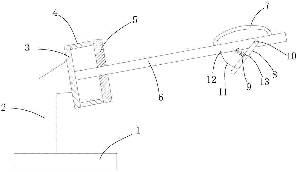
[0036] Such as figure 1 As shown, a shock absorber electrophoretic coating fixture includes a base 1 and a support frame 2 installed on the base 1, a support plate 3 and a sleeve 4 are installed on the support frame 2, and the support plate 3 and the sleeve 4 are both Made of steel, the support plate 3 is fixed with a support rod 6, the casing 4 is located on the periphery of the support rod 6, and the end of the support rod 6 away from the support plate 3 is equipped with a conductive block 8 and an arc-shaped conductive plate 7, the conductive plate 7 Made of steel, the conductive block 8 is a red copper conductive block, the first end of the conductive block 8 is hinged to the support rod 6, the second end of the conductive block 8 is an arc structure, and the conductive block 8 and the support rod 6 are provided with An elastic member that props up the conductive block 8 , and a limiting member that limits the swing range of the conductive block 8 is also provided between ...

Embodiment 2

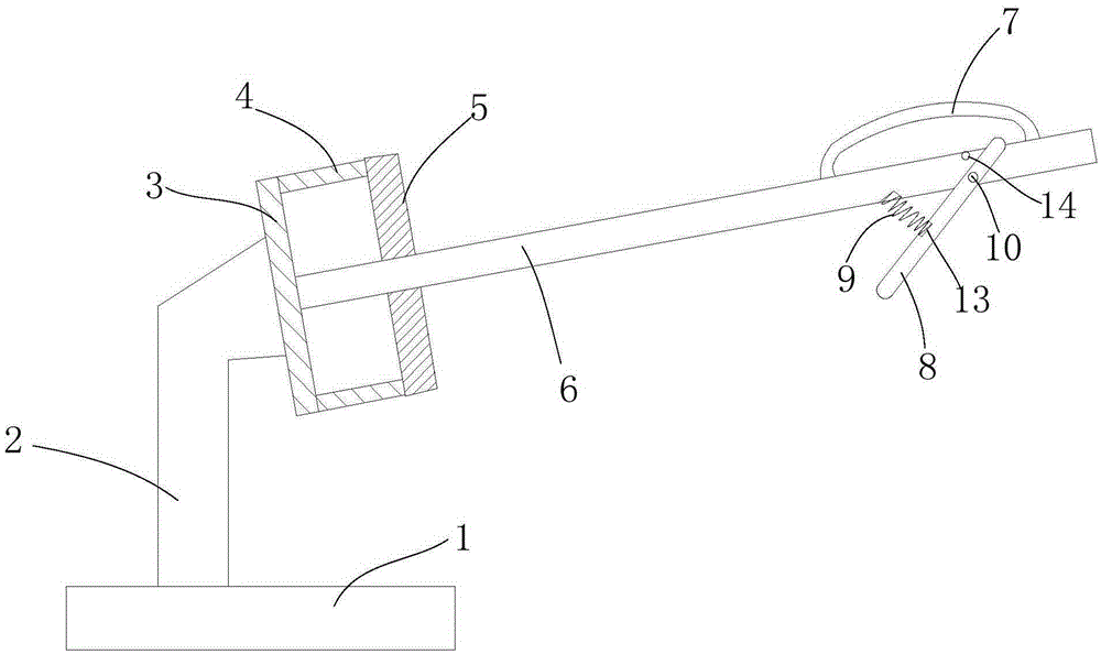
[0041] Such as figure 2 As shown, the difference between this example and Embodiment 1 is that the limiting member is a limiting column 14 arranged on the support rod 6, and the limiting column 14 and the elastic member are located on the same side of the conductive block 8, and the limiting column 14 and the elastic member are respectively located on both sides of the hinge point. When the compression spring 9 is propped up, the first end of the conductive block 8 abuts against the limit post 14 , and its maximum rotation range is limited by the limit post 14 .

[0042] In the present invention, the structure of the conductive block 8 is set, and the conductive block 8 is supported by the elastic member, which can ensure that the conductive block 8 is in contact with the inner wall of the shock absorber when the shock absorber is painted, and avoid poor conduction. Parts work together to limit the swing range of the conductive block 8, so as to avoid contact or too tight co...


PUM


Abstract

The invention provides an electrophoretic painting clamp for a shock absorber. The electrophoretic painting clamp comprises a base and a supporting frame installed on the base. A supporting plate and a sleeve are installed on the supporting frame, a supporting rod is arranged on the supporting plate, a conductive block and an arc-shaped conductive plate are installed on the supporting rod, the first end of the conductive block is hinged to the supporting rod, the second end of the conductive block is of an arc-shaped structure, an elastic piece used for supporting the conductive block is arranged between the conductive block and the supporting rod, and a limiting piece used for limiting the swinging range of the conductive block is further arranged between the conducive block and the supporting rod. A rubber seal is arranged between the sleeve and the supporting rod to guarantee that electrophoretic paint can not leak to the inner wall of the shock absorber. As the conductive block is arranged and supported by the elastic piece, it can be guaranteed that the conductive block makes contact with the inner wall of the shock absorber in the painting process of the shock absorber, and poor electric conduction is avoided; as the swinging range of the conductive block is limited under the combined effect of the elastic piece and the limiting piece, it can be avoided that the conductive block can not make contact with the inner wall of the shock absorber or makes contact with the inner wall of the shock absorber too tightly.

Description

technical field [0001] The invention belongs to the technical field of fixtures, in particular to a shock absorber electrophoretic coating fixture. Background technique [0002] In order to alleviate and attenuate the impact and vibration of the car due to the unevenness of the road during driving, to ensure the smoothness and comfort of driving, and to improve the service life and stability of the car, the car is equipped with a shock absorber. In the actual production process, the traditional electrophoresis line for automobile shock absorbers often has problems such as poor electrophoresis conductivity and electrophoretic paint on some areas of the inner wall of the shock absorber, and the production capacity of the traditional electrophoresis line for automobile shock absorbers is low. The main reason is that Because of the design problem of the fixture. [0003] In view of this, continuous improvement of the structure of the shock absorber fixture has become the main d...

Claims


Application Information

Patent Timeline
Patent Type & Authority Applications(China)
IPC IPC(8): C25D13/00C25D17/06
CPCC25D13/00C25D17/06
Inventor 曾明高尹正于
Owner CHONGQING MINGGAO MACHINERY CO LTD
Why Eureka
Try Eureka